In part one of Kettle Quest, I explained why I wanted a smart kettle and shared my disjointed journey trying to make a dumb kettle smart. After years of compromises and half-solutions, in 2024 I finally found a kettle marketed as being inherently smart and connected out of the box.
Third iteration: A shitty mass-market smart kettle
I can rant all day about how evil and dangerous Tuya is, but one thing I can credit them for is bringing cheap wireless modules to market. This has enabled Chinese manufacturers to churn out a huge range of inexpensive sensors and actuators, which in turn has forced innovation and price reductions among more reputable manufacturers.
I do own a few non-critical Tuya devices, but only Zigbee variants that can’t phone home. What I won't tolerate is anything that is inexplicably dependent on a cloud service with no verifiable security, which could be unavailable or permanently mothball my investment at any time, or that can be remotely controlled from outside my network or administrative control.
I once broke this rule and bought a Cosori air fryer with a Tuya WiFi module, intending to firewall it and use Tuya Local to control it. Instead, it intentionally stopped working even locally when it couldn't reach the mothership. Worse, while they proudly announced their safety afterthought that they had disabled remote start (something I imagine was actually forced on them by a regulator), this was only changed in the UI; the actual firmware would still turn on by remote command. I won't have a device that can be commanded to burn my house down remotely from China, so I returned it.
Smart kettles are not really prevalent yet; I don't know why. In 2024, the only one I could find with any kind of remote control was the WeeKett. Previously there was also a Proficook, but they no longer sell in the UK. Both were WiFi only, no Zigbee, so I reluctantly decided to give the WeeKett a try.
As I understand it, WeeKett was designed at the University of Edinburgh, not in a Chinese sweatshop, so there's really no excuse besides laziness to be using the Tuya ecosystem. At a retail price of £85 and with a sub-£4 BOM for the electronics, there was plenty of scope for using something more robust and professional for a device that's switching a 2200W heating load.
Nevertheless, being the only option available, I thought I would get it, firewall it, and control it with Tuya Local (which controls the device directly using Tuya commands over the LAN, not via the cloud). The device descriptor showed all the endpoints it exposed, including temperature control, so I should be able to control all of its functionality without having to open the kettle up. Failing that, maybe I could flash Tasmota (although as I later discovered, it's neither ESP-based, nor can tuya-cloudcutter break it).
I put it on my internetofshit VLAN (with no internet access), set up Tuya Local, and hey presto, I could remotely control it, and I started writing automations.
Within a day, the communication module stopped working. The kettle itself would respond to the front-panel buttons, so it could still be used manually, but it didn't connect to my WiFi network. Factory reset didn't help, and it wouldn't enter pairing mode.
I returned it and got a replacement. But the same thing happened. At first everything was great, then within two days it had bricked itself.
I was initially suspicious that it was somehow retaliating for not being able to communicate with the Tuya cloud, but in a more severe and permanent way than the air fryer had. The truth, as I discovered later, is rather more disturbing.
By this point, I had passed my 30-day return window and, while I could have made a fuss about my consumer rights, I had half a mind that one day I would go back to my plan from the previous iteration and simply wire a relay across the boil button when I next had some time to spare.
Tear it down
Opening the kettle base was an ordeal. I spent the better part of a month occasionally attacking it with various tools while trying not to destroy the casing. To an extent, I can respect the mechanical build quality here; you don't want consumers opening up a kettle. Unfortunately, that's where my respect ends.
Inside are three PCBs, which I'll call the power board, controller board, and comms board:
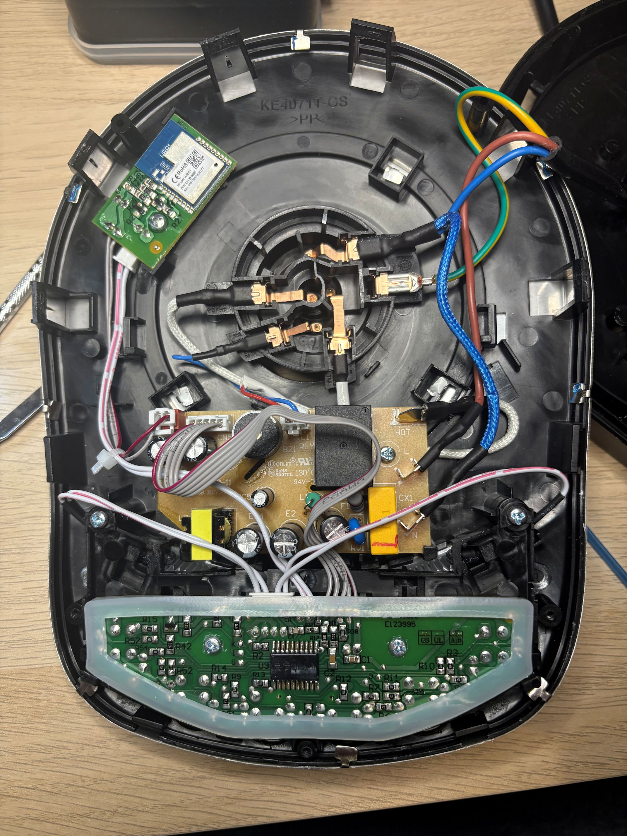
The power board in the middle has the mains connection, a relay, buzzer, a concentric ring connector to the kettle body (neutral, switched live, earth, and the thermistor), transformer and a 3.3V regulator and a 5V regulator, and associated circuitry. This is the only board with conformal coating.
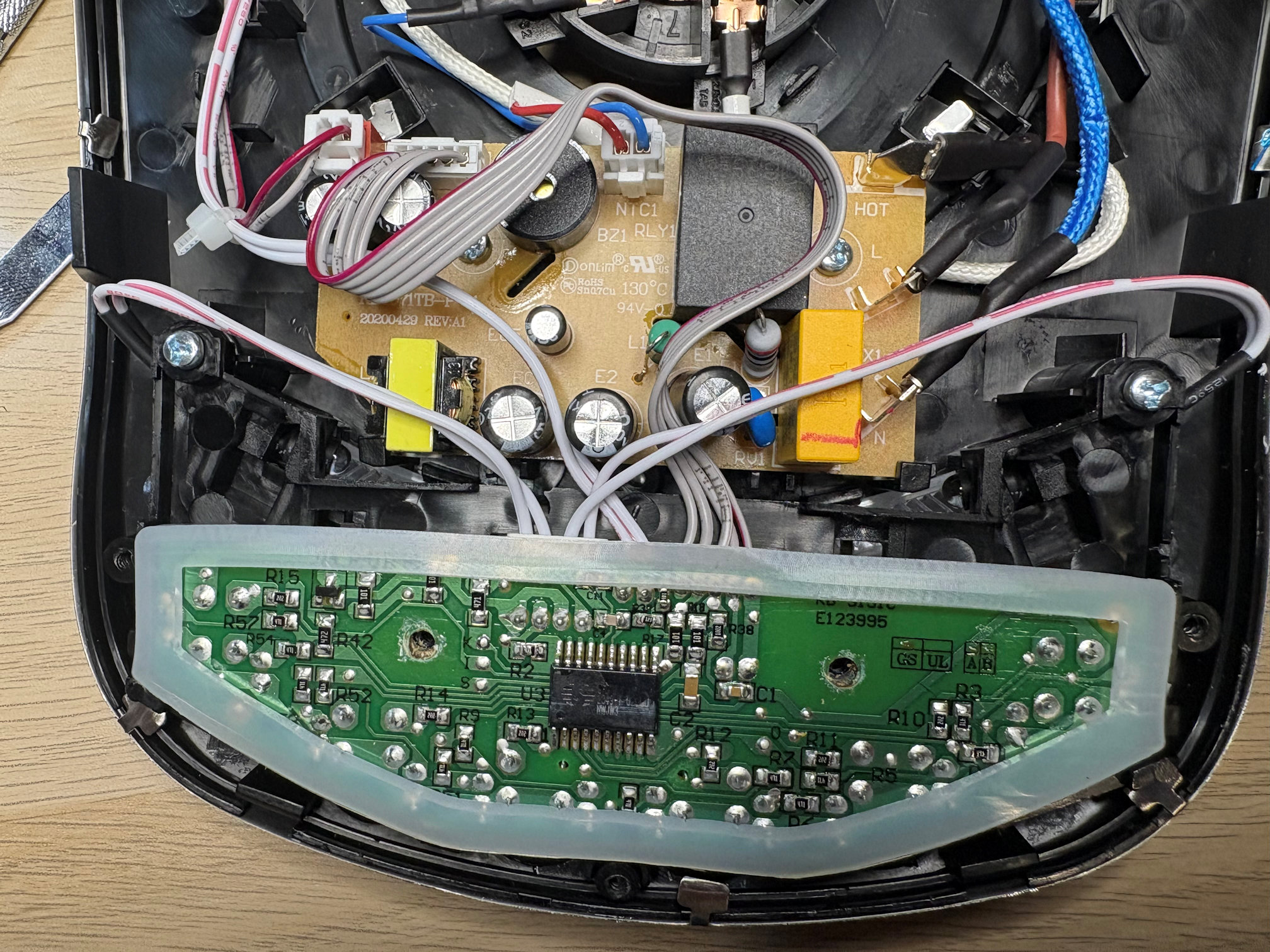
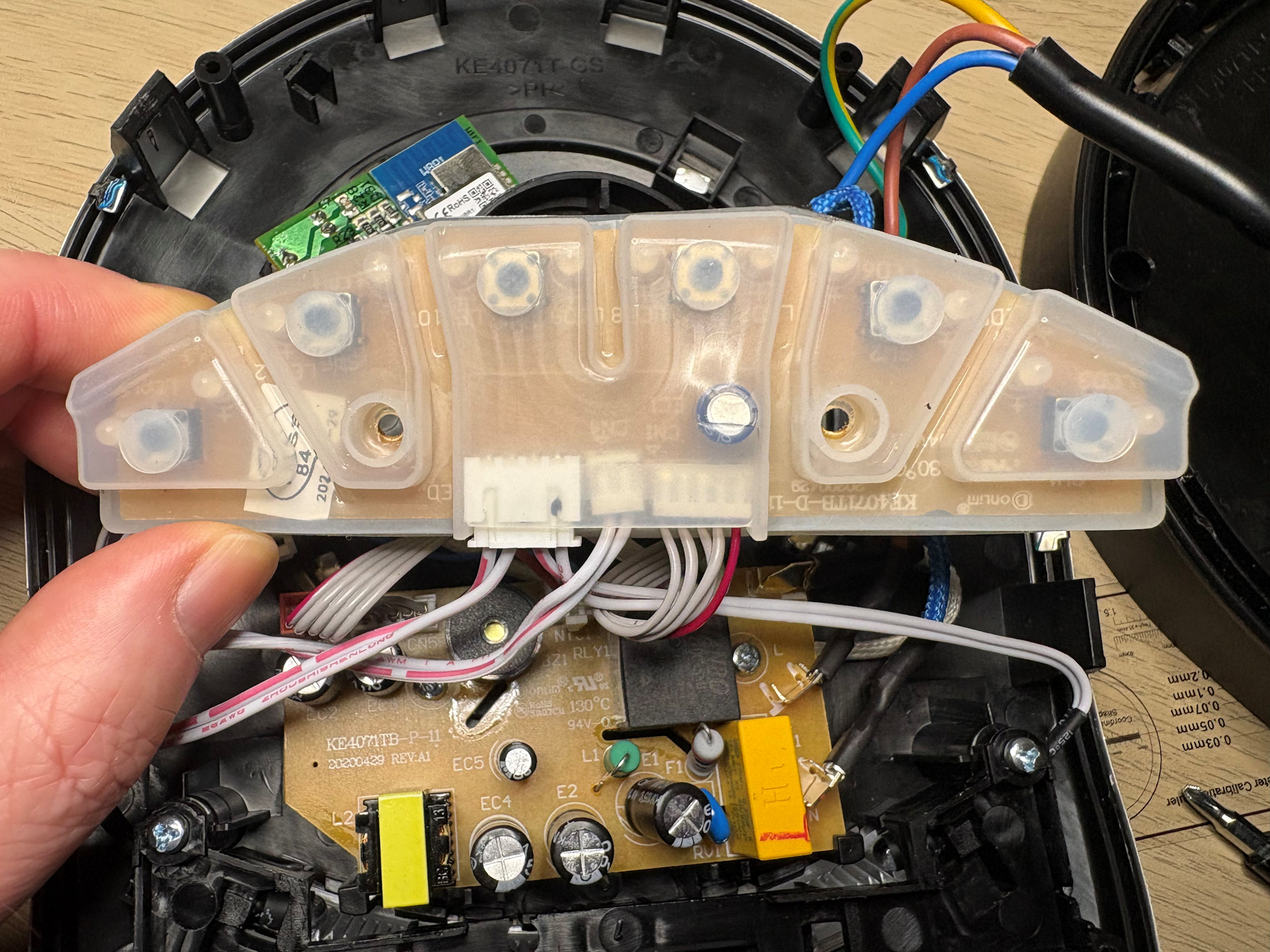
The controller board at the bottom runs at 5V, and has a SH79F3212M processor (an 8-bit 8051 clone, which rather betrays this device's heritage as a student project) and nothing else besides passives. It is capable of operating the kettle entirely on its own in manual mode without the comms board present. It's on the underside of the PCB with the kettle buttons, so it has those as input. It has a ribbon cable connecting it to the power board, which besides power also interfaces with the relay for heating control, the thermistor for temperature sensing, and the buzzer which is also off-board. There are a couple more ribbon cables connecting LEDs, and a final ribbon cable connecting to the comms board.
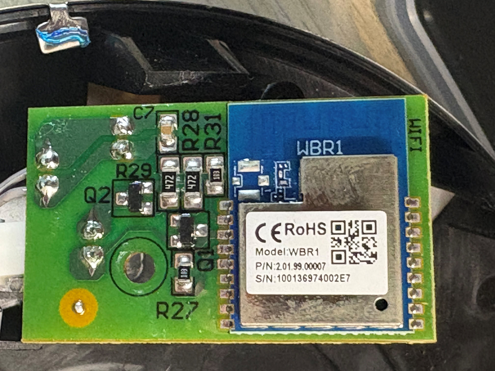
The comms board at the top left runs at 3.3V, and is almost comically simple, being nothing but a carrier for a Tuya WBR1 WiFi module, plus a couple of level shifters (BSS138 I assume, or something pinned the same, but the board has no 5V supply so the HV pull-ups must be at the other end) and associated passives. One two-pin ribbon cable (of one AWG and pin pitch) goes to the controller board TX/RX, and the other (of a different AWG and pin pitch) get 3.3V and GND from the power board.
Debugging the Weekett
Except actually it doesn't receive 3.3V.
While carefully tracing the circuitry with a multimeter, I observed that there was no voltage on the 3.3V rail. This was a bit of a WTF moment, as a lack of power to the WiFi module clearly explained why WiFi was not working. Some short on the comms board? No, 3.3V is still missing on the power board with the comms board disconnected. Had Tuya's desperate attempts to call home perhaps used so much power it had blown something on the power board?
I needed to trace the power board to find out why. I removed it from the mounting and flipped it. I knew it had been unplugged for weeks so the capacitors would be empty.
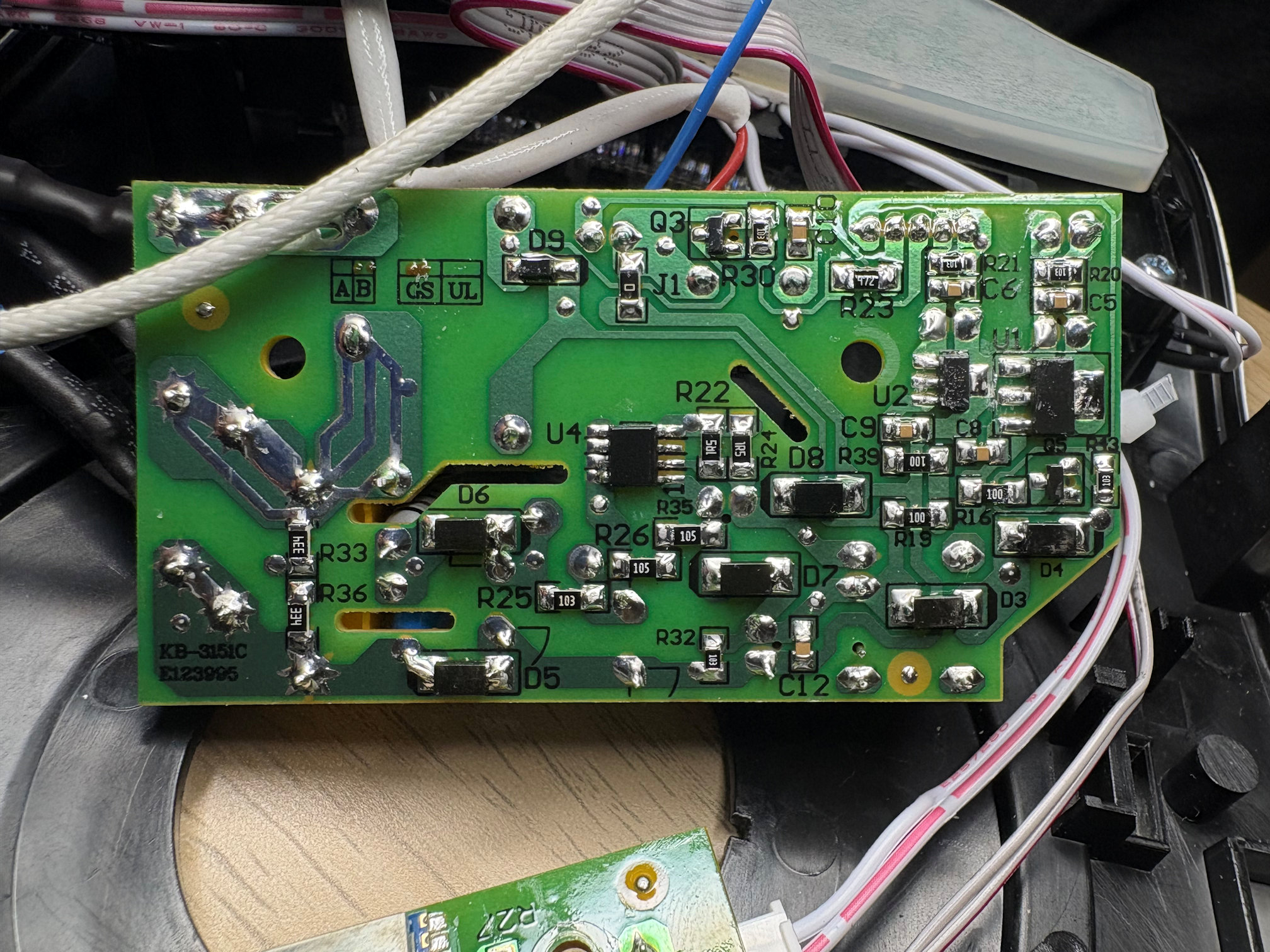
U2 is the 5V regulator, a 78L05. I didn't even need to look that up, I recall using those in school - [cough] decades ago - and it is ingrained on my memory. Pin 1 is Vout, pin 2 is GND, and pin 3 is Vin. Pin 1 of the regulator is correctly delivered to pin 2 of the 5-way connector CN5 to the controller board. Pin 2 of the regulator and its body are correctly at ground, continuous grounds I found elsewhere on the board, and are delivered to pin 1 of CN5. Pin 3 comes via 2x 10Ω resistors R39 and R19 (that I feel are just being used as jumpers to avoid a double-sided board and therefore should have been 0Ω) from the transformed but unregulated output which I found on the left side of D3 (not passing through D3).
U1 is the 3.3V LDO regulator. Strangely, they have gone for a larger package here, but maybe they had students hand-soldering these and they didn't want any chance of them getting mixed up. It's a FH1117S-3.3, a Chinese knockoff I'd never heard of, presumably a clone of the NCP1117, and like many Chinese parts, finding a datasheet from a reputable vendor or from the manufacturer is impossible. But I did find one that indicates its pinout, at least for the SOT-223 version: pin 1 is GND, pin 2 is Vout, and pin 3 is Vin. I've mirrored the FH1117S data sheet for reference. This slightly unusual pinout is the reason I initially suspected a PCB layout issue.
I traced these pins on the board. U1 pin 1 ground is connected to pin 2 of the 2-pin output connector CN6 (swapped polarity from the 5-pin connector; weird but okay), and U1 pin 2 is connected to pin 1 of the output connector. The body is connected to Vout, pin 2; it's not just internal as the PCB takes Vout from the body pad too.
In the other direction, pin 1 ground has continuity to the same ground of the 5V regulator and elsewhere. The last thing to trace was pin 3, Vin. It connects to C8 okay (decoupling capacitor to ground) and through another 10Ω jumper resistor to pin 3 on a unlabelled SOT-23 chip Q5. Tracing the other pins of Q5 shows pin 2 connects to the same unregulated supply through two sequential diodes D3 and D4 (presumably to drop the voltage a bit), and pin 1 loops around the body and around the board edge all the way to pin 5 of CN5, the 5-pin connector to the controller board. There's a 10kΩ pullup towards that chip's pin 2 too. Okay, so pin 1 (base) to the controller, pin 2 (emitter) to the power source, and pin 3 (collector) outputs to the regulator.
Aha. So Q5 is a PNP transistor, allowing the controller to control the input to the regulator that supplies the comms board, and it drives the base low to turn power on.
Could it be this simple? Is the controller board actually actively denying power to the comms board, despite seeming to be functional in other respects (buttons work, kettle boils manually)? And despite actively communicating datapoints to the comms module during this time, and accepting commands from it?
Testing Q5
The test of my understanding of this circuitry was to disconnect the 5-pin jumper to remove the comms board entirely. Not wanting to turn on the mains with the board in pieces, I supplied 6V between D3 and D4 (so I would only be supplying the 3.3V circuitry). As expected, with pin 5 of CN5 disconnected, it was pulled up to Vin and there was no output from the regulator. With pin 5 pulled to ground, the regulator output a perfect 3.3V.
So yes, the controller is firmly in control. It's actively denying power to the comms board, even after doing a "factory reset". In simple terms, the WeeKett kettle is actively and deliberately turning off its own WiFi module.
Workarounds
At this point, I could have bypassed Q5 to keep the 3.3V supply permanently on, and it would probably have worked, although I would still have been stuck with a Tuya module. This is what I'd recommend to anyone looking for a quick repair: either connecting pin 5 of CN5 to ground to keep the power signal permanently on, or bypass Q5 by bridging pins 2 and 3 - I'd probably go with the latter, so the controller MCU isn't potentially trying to drive high a ground pin.
But by then I was already planning a more satisfying solution: ripping out the Tuya module entirely and replacing it with something under my own control, which would take an unswitched 5V. But at least I had shown that there wasn't a fault in the regulator, or (as I initially assumed, prior to finding a FH1117S data sheet), a dangerous miswiring that had caused it to burn out after a while, either of which would have necessitated removal.
But... WHY?
I honestly don't know why this circuitry even exists - why does the controller need to control power to the comms board? I thought it might be something to do with the factory reset (the factory reset is holding a button on the controller board), but you can't cause a factory reset just by flipping the power, there must be some UART communication for that as well (indeed there is, command 0x05). Is it to soft reset the module if heartbeats are missed, in lieu of using the reset pin like it's actually supposed to? Perhaps, but why is it then permanently disabling the comms board despite receiving heartbeats? In the absence of a good reason, it would have been better to avoid having this circuitry entirely and risking the flaw it has led to. After all, if the Tuya module needs a soft reset, the user can always power cycle the whole kettle.
This is likely therefore to be a software issue and something Weekett could have easily fixed with a firmware update, albeit not for already-shipped products (even if it did have the ability to update controller firmware via the Tuya interface, which I don't think it does), so it wouldn't help people who have already bricked their kettle simply through normal use.
Why, in August 2024, were Weekett support still claiming "the kettle base may have a fault, which is quite rare", despite the voluminous public complaints and reviews?
Quality control
This raises so many questions:
- How did this not get caught at any stage of design or review?
- Why did it not surface during testing?
- If the prototype used a different part that responded differently, why was it not picked up when the production models started arriving?
- Given I bought it in July 2024, a full 2.5 years after it went on the market, how was a pattern not correlated from customer complaints during that time?
- How had nobody at WeeKett or the University of Edinburgh taken one of the many, many returned units and done the basic diagnostics I've done above — which would have been even easier for them with the actual schematics to hand?
- Why, in August 2024, were Weekett support still claiming "the kettle base may have a fault, which is quite rare", despite the voluminous public complaints and reviews.
- Why did they send me a replacement with the same fault?
- Why has there not been a full product recall?
- Why is there still no public information or admission or contrition from Weekett?
Weekett: If you have a statement you would like to make about this issue, I will post it below, but so far your offshore customer service aren't even admitting there is a problem. You should also offer a firmware update for those who have the ability to flash the SH79F3212, and a swap for those many, many consumers who have a bricked device.
Further thoughts
Interestingly, on the 5-wire connector to the controller board, I had initially assumed the 3 non-power pins were directly connected to the relay (controlling heating element on/off), the thermistor, and the buzzer. But having now identified one of the three pins is solely controlling the 3.3V regulator, the other three functions are being controlled by only two wires, implying an I2C slave or something. Indeed, the only chip remaining on the power board is U4, which doesn't have any helpful markings ("04937A"), but which I assume is an I2C I/O expander or similar. I don't plan to replace the controller board, so I don't particularly see the need to trace this further.
The PCBs look like they've been designed by hand on a light box, and while it's charming that they're still teaching hand-crafted PCB design at the University of Edinburgh, there isn't really an excuse for this student project not to have been reimplemented with an EDA tool before becoming a consumer product. If it hadn't been designed by hand, there would also not really be any reason to try to force a single-layer PCB with jumper resistors, given the minuscule incremental cost for a two-layer PCB versus the absolutely staggering margin they are putting on this product (sustained due to lack of competition) - and there's no excuse for using the wrong value of jumper, introducing unnecessary resistance into the circuit.
The separation between high voltage and low voltage components on the power board leaves a lot to be desired; indeed there are several components that don't belong on that board at all (such as the buzzer and I2C expander) and there's no input protection, so a dent or short on the kettle's concentric ring connector could lead to live being shorted to the directly-adjacent thermistor pin on the low voltage circuitry leading right to the MCU.
The reference designators are all over the place; there are nowhere near 43 resistors on the board, yet the highest resistor is R43. The only transistor or Q-numbered part is Q5 rather than Q1. Perhaps they are sharing designators between boards despite them being different parts number, but even if one could accept the shockingly discontiguous numbering that jumps around between boards, there are still gaps in the numbering.
The kettle body is earthed via the concentric ring connector, but weirdly the equally conductive metal fascia of the base plate is not. One could argue that the base is double-insulated, but then so presumably is the kettle itself. Why should one metal plate be earthed and another, a few mm away, not be? It would have been trivial to earth both.
The kettle happily heats while empty for a dangerously long time; even dumb kettles have boil dry protection, why does this smart kettle not?
Finally, apart from the sloppy 10Ω jumper resistors, there are also 10kΩ resistors directly across both the 3.3V and 5V output rails that have no purpose but to sit there quietly wasting electricity.
Altogether, it feels very much like the electronics have gone straight from a student project prototype to mass production without any intervening refinement or review. The physical/mechanical side is to a better standard, but I suspect it wasn't designed from scratch as it has nothing unique or that hasn't been done before, so they may well have worked with someone else's existing design - a supposition backed up by the fact that the internal moulding has standoffs and clips that aren't used in this model.
Schematic
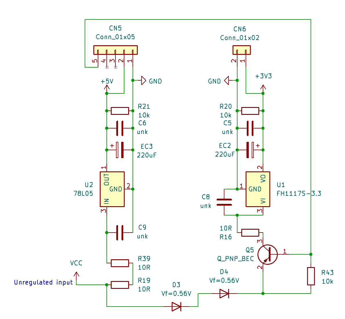
Having done all this work to trace the regulation side of the PCB, it would be remiss of me to not produce a schematic of what I've learned for anyone who follows, so here it is, and you can download a PDF or KiCAD schematic on Github.
Next steps
Having sunk my money into this product, I thought I could proceed having now identified the problem and a workaround, despite the product's flaws. I would replace the comms board, and steal myself a 5V supply that wasn't dependent on the controller being in a good enough mood to grant me power. Join me in part 3 where I hack the WeeKett!