In part one of Kettle Quest, I explained my reasons for wanting kettle automation and some of the early solutions I had explored to reach my goal. In part two I found an off-the-shelf product in Weekett that promised me a ready-made solution, but turned out to be a huge disappointment that has defrauded thousands of consumers by turning their smart kettles dumb. In this third part, I'll go into the detail on how I turned that around over the past few weeks, hacking it into something that is actually functional, and in the final part I'll talk about the software, draw some conclusions and make some recommendations.
Fourth iteration: Weekett hacking
So my Weekett had bricked itself into a non-smart kettle, and while I still had my last-resort option of just wiring a relay across its "boil" button, I knew I could do better.
Initially when I first got the kettle, I had thought I would be able to reflash the Tuya module with Tasmota or ESPhome, but it turns out my assumption that this was ESP8266-based was wrong - the WBR1 has a KM4 MCU - so I would need to replace the whole module with one of my own making anyway.
First, I needed a power supply that wasn't reliant on the broken controller firmware's whims. I needed to either bypass the transistor on the power board to wire the 3.3V output permanently on, or I needed to derive my own power supply. I opted to do the latter, as I didn't really want to be messing with the board that also had mains power on it. I also ideally wanted 5V rather than 3.3V anyway.
Next, I needed to know how the Tuya module communicated with the controller board. I could already see that there were level shifters connected to the Tuya UART pins, so it was serial, and I assumed it would be the standard Tuya MCU protocol. I flashed an ESP32-C3 supermini with Tasmota and connected it via a commodity BSS138-based level shifter board to the controller's UART pins.
Given my previous electrocution, I deliberately did not power the kettle from mains during any of this. The ESP32 was powered by USB and, as I intentionally omitted diodes, it backpowered the controller board from VBUS so I could test the whole low-voltage circuitry.
After a fair bit of messing around figuring out how to configure Tasmota, and after learning I needed "Weblog 4" to get debugging output, I magically saw a bunch of dpIds emitting data, matching those identified in the Tuya Local device descriptor.
Omitting the super-debug lines, the relevant lines showing dpIds being received at pace were like this:
00:15:37.340 {"TuyaReceived":{"Data":"55AA03070005010100010011","Cmnd":7,"CmndData":"0101000100","DpType1Id1":0,"1":{"DpId":1,"DpIdType":1,"DpIdData":"00"}}}
00:15:37.351 {"TuyaReceived":{"Data":"55AA03070008020200040000000019","Cmnd":7,"CmndData":"0202000400000000","DpType2Id2":0,"2":{"DpId":2,"DpIdType":2,"DpIdData":"00000000"}}}
00:15:37.372 {"TuyaReceived":{"Data":"55AA0307000803020004000000001A","Cmnd":7,"CmndData":"0302000400000000","DpType2Id3":0,"3":{"DpId":3,"DpIdType":2,"DpIdData":"00000000"}}}
00:15:37.383 {"TuyaReceived":{"Data":"55AA03070008080200040000006483","Cmnd":7,"CmndData":"0802000400000064","DpType2Id8":100,"8":{"DpId":8,"DpIdType":2,"DpIdData":"00000064"}}}
00:15:37.404 {"TuyaReceived":{"Data":"55AA0307000809020004000000D4F4","Cmnd":7,"CmndData":"09020004000000D4","DpType2Id9":212,"9":{"DpId":9,"DpIdType":2,"DpIdData":"000000D4"}}}
00:15:37.416 {"TuyaReceived":{"Data":"55AA030700050C040001001F","Cmnd":7,"CmndData":"0C04000100","DpType4Id12":0,"12":{"DpId":12,"DpIdType":4,"DpIdData":"00"}}}
00:15:37.425 {"TuyaReceived":{"Data":"55AA030700050D010001001D","Cmnd":7,"CmndData":"0D01000100","DpType1Id13":0,"13":{"DpId":13,"DpIdType":1,"DpIdData":"00"}}}
00:15:37.436 {"TuyaReceived":{"Data":"55AA030700050F0400010022","Cmnd":7,"CmndData":"0F04000100","DpType4Id15":0,"15":{"DpId":15,"DpIdType":4,"DpIdData":"00"}}}
00:15:37.446 {"TuyaReceived":{"Data":"55AA03070005130500010229","Cmnd":7,"CmndData":"1305000102","DpType5Id19":"0x02","19":{"DpId":19,"DpIdType":5,"DpIdData":"02"}}}
00:15:37.466 {"TuyaReceived":{"Data":"55AA03070005650100010075","Cmnd":7,"CmndData":"6501000100","DpType1Id101":0,"101":{"DpId":101,"DpIdType":1,"DpIdData":"00"}}}
Ones that immediately stand out are dpId 8 with value 0x64 (100 decimal), which the Tuya Local descriptor confirms is the temperature setpoint, dpId 9 with value 0xd4 (212°F setpoint), and dpId 19 with value 0x02, a bitfield indicating problems, and this bit presumably indicates the kettle is off-hook.
I performed a few test writes and they worked too (although I could not actually turn the kettle relay on, which I think is not due to lack of mains, but because the controller sees no thermistor reading and knows the kettle is not on its base).
So I would be able to control it in fundamentally the same way I had with Tuya Local - the Tuya module is simply passing through messages to the controller - either by implementing the Tuya serial protocol myself, or just passing messages through from Home Assistant. Fabulous, concept proved.
Now I just needed to replace the communications board (both Tuya module and carrier) entirely. I initially wanted to make revision 1 with Veroboard, but there was not enough vertical space inside the kettle base to carry the DIP footprints of an ESP32 module and a level shifter above the board.
Revision 1.0 hardware
It was time to design a PCB. I've done this a few times before, more than a decade ago, for some modules for my previous flat's 1-wire bus, and I could get a PCB up to 5x5cm back then for a paltry $10 plus shipping for 10 units, so I knew this wasn't going to be a costly prospect. These days, it's even cheaper and faster.
I wanted to use an existing ESP32 module to make my life easier, so I wouldn't need to design and build all the supporting circuitry for the MCU. I decided to use a Seeed XIAO ESP32 module rather than a Supermini, because it had sufficient pins, and was castellated so it could be soldered directly to the board, both for a lower profile, and to avoid protruding pin headers. For the specific variant, I went for an ESP32-C3, because I didn't need the power of an ESP32-S3, and I didn't need the Zigbee function of the ESP32-C6: I would need WiFi anyway to flash firmware remotely without having to open the kettle, and being a mains-powered device, I didn't particularly see a need to also have low-power Zigbee. I also wanted an external antenna rather than relying on a chip antenna, given the kettle base was made of metal, so I didn't need the chip antenna from the C6 and the U.FL connector of the C3 was sufficient.
For ESP32 variant quick comparison, the best resource I've found is espboards.dev (although their comparison table at the time of writing mistakenly claims that the H2 doesn't have 802.15.4 support, which is kinda the whole point of this variant, an error that I've reported to them).
It’s been about a decade since I last designed a PCB in Eagle. These days Eagle isn’t just no longer free, it’s been discontinued entirely, so I needed to learn something new. Of the available options I chose KiCad which, while not the most advanced (it lacks built-in autorouting, for example), seemed the most likely to remain free and free of vendor lock-in. As you get older, you realise what a waste of time it is constantly learning tools just because vendors get greedy and force you to move. It kills productivity to just stand still. I value my time more every year and avoid unnecessary change - I still use PaintShop Pro as my bitmap editor! So I wanted this to be the last PCB editor I have to learn, and I don’t want to discover in another decade that I can’t even open my own designs anymore, like I can’t with my old Eagle files. KiCad is open source with a long history of open stewardship, so hopefully it’s the right choice.
The board design would be very simple: a carrier footprint for the XIAO module, two level shifters for the UART, and two board to board connectors, one serial and one power. The serial connector on the original board is already 2.54mm pitch; given I would need to replace the source of the power anyway due to the 3.3V regulator being unusable, I took the opportunity to switch this to XH 2.54 as well. This board takes 5V rather than the original comms board's 3.3V; the XIAO module's on-board regulator is used to provide the 3.3V rail. But I still needed to level shift the UART pins between 5V and 3.3V since the ESP32 itself is 3.3V.
I did my first prototype PCB with Seeed, who I also used back in the day. It cost $4.90 + $5.97 shipping ($10.87 total) for 10 boards. I ordered on 22 January, it was manufactured by 27 January, and I received it on 3 February (12 days). This was not too bad, and not a problem, as I got busy around this time and didn't get round to ordering the components from CPC until later anyway.
More disappointing was Seeed's shipping of their own XIAO modules, which I ordered on the same date 22 January, but didn't receive until 13 February (22 days). Shipping from China really isn't hard these days. I order on a weekly basis from Aliexpress nowadays, and everything arrives in 4-5 days. Aliexpress pre-clear customs by charging VAT at source, and consolidate shipments and deposit them directly with Evri. It is remarkably impressive. Yet, even though Seeed have a store on Aliexpress, they charge a shipping fee there (even more than on their own store), which to me implies that they don't use Aliexpress shipping and still use their own carrier, so I wouldn't get it any faster that way.
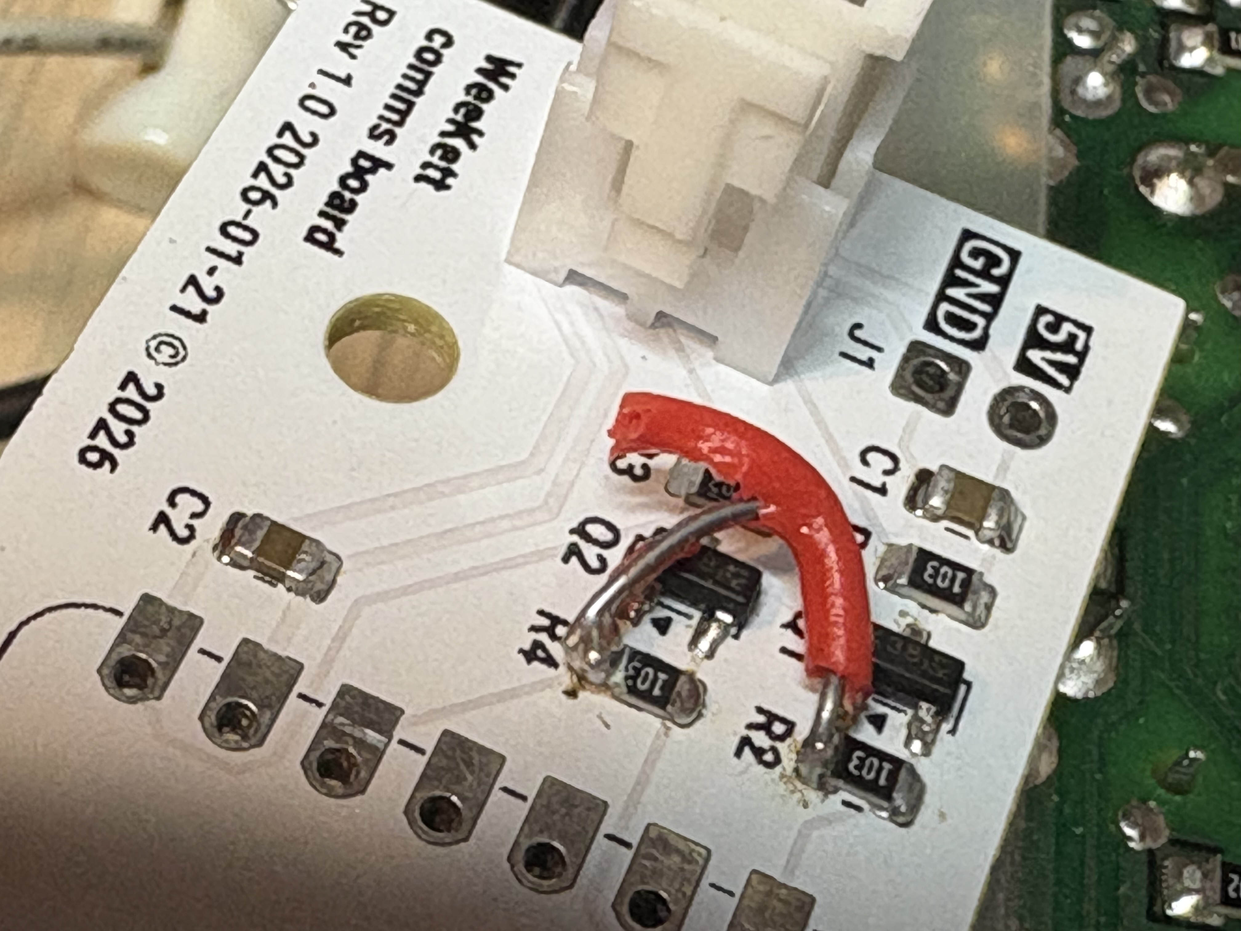
I chose 0805 and SOT-23 components, which I used to be able to solder fine, but being a decade out of practice and with somewhat worsened eyesight these days, I did a rather bodge job of it. I did get the components down though. Testing with a multimeter did not produce the expected results on one pin, and it turns out there was a missing trace between Q1's gate and 3.3V:
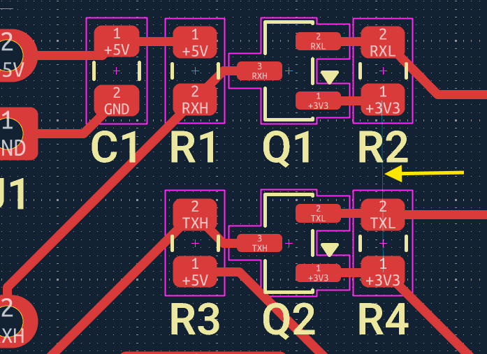
How did this happen? Well, for one thing, that ratsnest wire is so thin and faint as to be almost invisible (the yellow arrow was added by me). It should have, and indeed did, show up on the DRC check. But, first of all, it's on a different tab of the DRC check. And second, I removed that trace quite late in the day to reroute it, and by that time I was getting fatigued being inundated with irrelevant DRC warnings: numerous errors about silkscreen overlapping board edge in places where I don't actually have silkscreen, numerous warnings about outline font thickness about the font I'm using that it doesn't understand and is plenty big enough, and numerous warnings about silkscreen crossing the castellated pads on the vendor-supplied footprint, which is fine as it will get removed on plot. So amongst those irrelevant errors, I missed an important one. I will have to check more thoroughly in future. As a network engineer by trade, this concept is familiar to me as "monitoring fatigue" - the more alerts you get that are not correct, relevant, and actionable, the more you are likely to ignore all alerts and miss ones that are actually important.
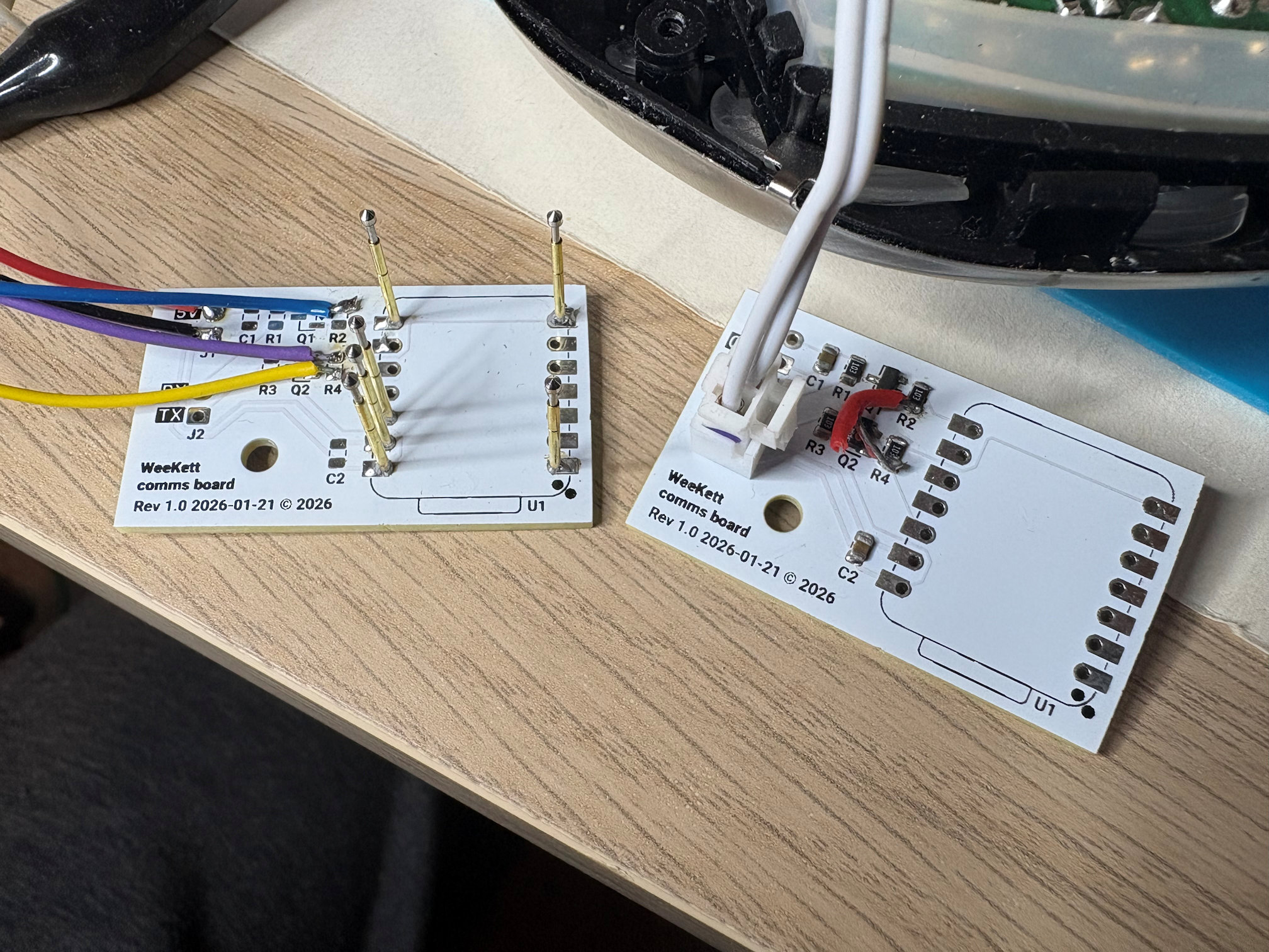
At any rate, that's why there's a red wire in rev 1.0 (which I also couldn't get enough heat into to solder before the jacket melted). I didn't solder the XIAO module onto it as I didn't want to waste a module on a PCB with errors, so I just used pogo pins to test the circuit. But it works fine.
There is no diode on the 5V line and this is intentional, so the kettle controller board can be powered by the XIAO while I'm debugging via USB. But it does mean that it's critical that the power board isn't powered while USB is connected. That's fine by me, as for my own safety I don't intend to apply mains again until I have finished and closed the kettle up.
Revision 1.1 hardware
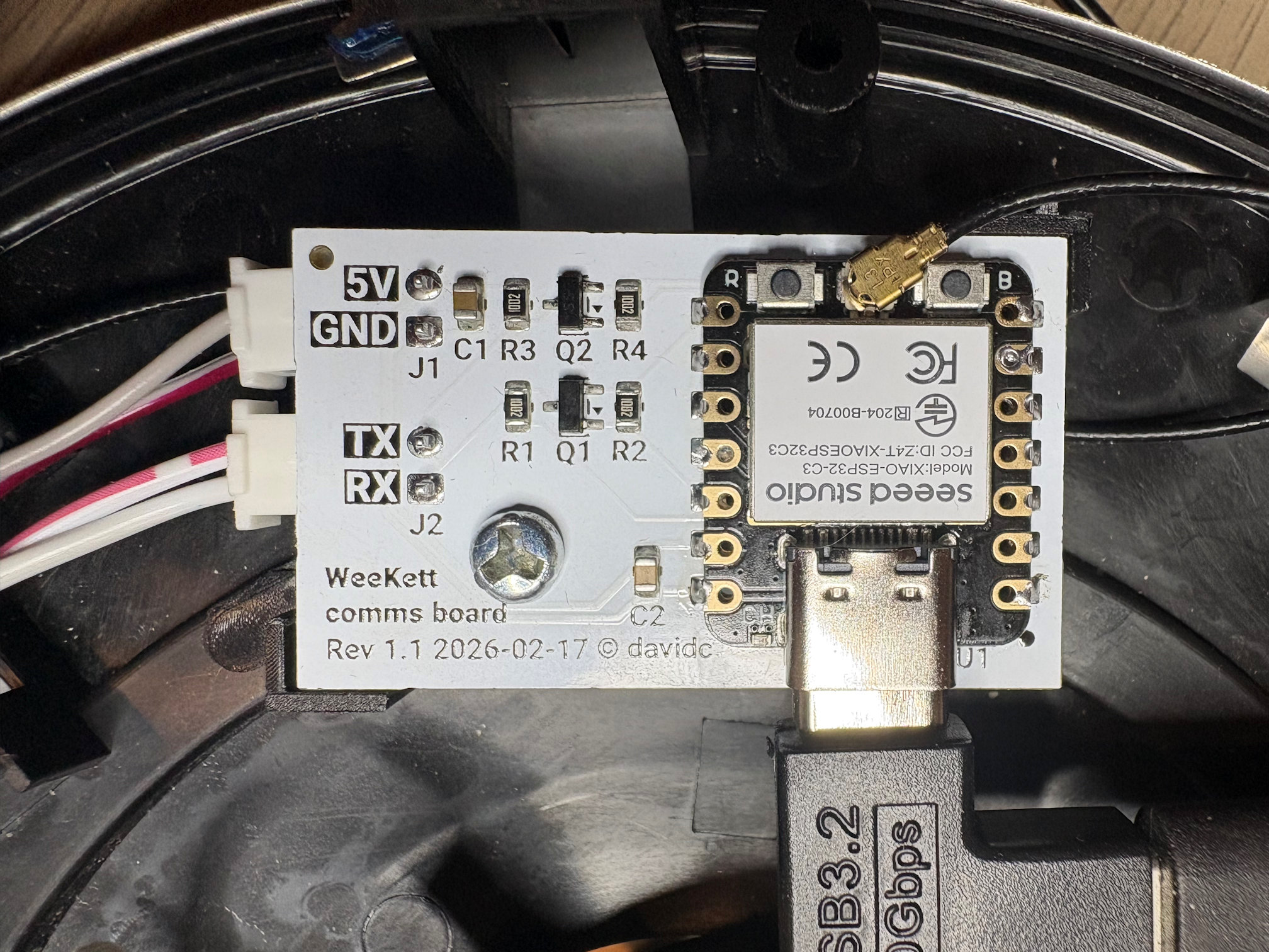
A rev 1.1 PCB was needed. I took the opportunity to swap the position of TX and RX, because I decided I wanted the connectors on the underside of the board with angled connectors to use less space. This also simplified the trace routing. A few other minor adjustments - I moved the screw hole 1mm to better align with the mounting shown when test-fitting rev 1.0, moved the terminals a little inward, increased the font size. I ran a full DRC and carefully pored over every warning before plotting.
I also wanted to do a better job soldering this time around. I bought myself a neat little £10 USB PD65W hot plate from Aliexpress and some flux and solder paste. I also bought a Fnirsi HS-02A soldering iron with smaller tips. But in the meantime I discovered how insanely cheap PCBA (PCB assembly) is these days.
I switched from Seeed to JLCPCB as their PCBA was significantly cheaper. I paid an incredible $2.00 for PCBs, $1.46 for PCBA, and $1.50 for shipping - so a total of $5.96 for 5 PCBs, including the surface-mount components, including the assembly, including the shipping, and even including 20% VAT which JLCPCB collected (which Seeed should have but do not). This includes a new user discount, but it also appears that they issue a generous set of coupons every month anyway.
I ordered on 17 February, the PCBs were fabbed by 22 February, assembled by 24 February, and in my hands on 4 March (15 days all told). This was also affected by Chinese New Year occurring during this period - although they advertised that 2-layer PCBs would not be impacted, my order status indicated that it was. This wait was agonising, as I could feel how close I was to the end. Still, for $6 I can't complain at all, and I can expect in future for it to be even faster.
Compared to the Seeed boards, despite the fact that my traces were 0.5mm for power and 0.3mm for signal in both v1 and v1.1 Gerbers, my initial visual check suggested that the JLCPCB traces are visibly thinner, and I couldn't see a difference between the two trace widths on that board. Yet in the photograph here, I can see a difference between trace widths, and both PCBs look similar. I wonder if this is an optical illusion caused by JLCPCB maybe applying a higher density of solder mask?
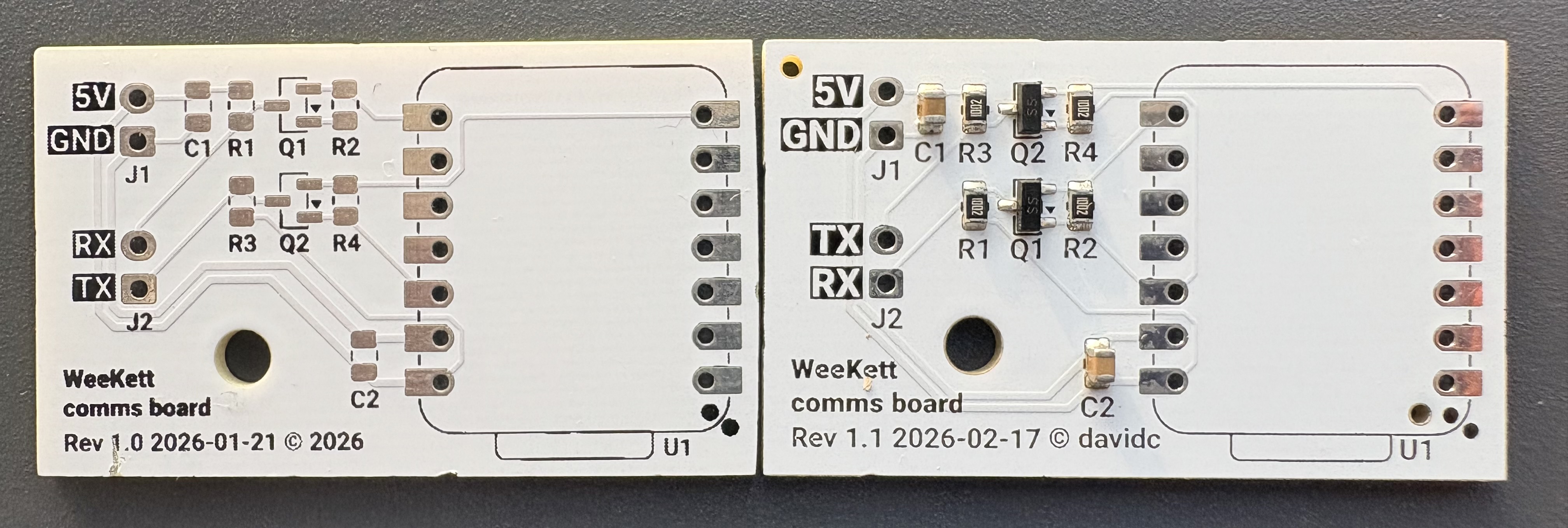
The other main difference is that the JLCPCB boards don't have particularly straight edges, they have indents from the panelisation. I assume this is because my board order shows "no" to deburring: I am not sure why, as it defaults to on, and I don't recall turning it off, and it costs a mere £0.07 so I don't know why I would have. On the other hand, my Seeed boards have chips at the edges, and edges are slightly curved at one end where someone has presumably pushed them up against a sanding belt and removed them not quite parallel. However, neither defect is significant and is within tolerance.
The JLCPCB board also more clearly shows up a defect in the silkscreen plotting that is entirely the fault of KiCad. I originally assumed that KiCad was doing this on purpose because it thinks silkscreen is actually ink through a screen (similar to solder paste through a stencil) and wanted to avoid over-saturation of ink in dense areas, but it's actually not been silkscreen for a very long time. I actually now think, looking at the close-up of the curves that cause this negative area, that it just doesn't understand the overlaps my outline font (Roboto) uses. Corroborating this assumption is the fact that those negative areas only appear in the output Gerbers, not on screen where the font is presumably being plotted by OS routines instead.
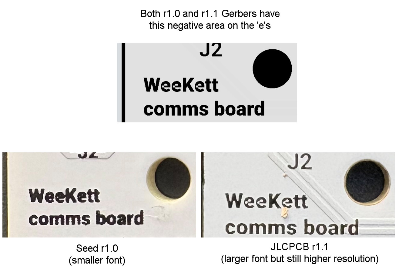
The silkscreen resolution with JLCPCB is much better. To be fair, this is not a direct comparison as I increased the font size in rev 1.1, but even so, the photo above shows the same-sized board area on both PCBs, and JLCPCB's is clearly less smudgy, which in turns allows the negative areas to show up.
PCBA is amazing. I never thought I'd be able to afford it last time I was designing PCBs. But at today's prices, and with my degrading eyesight, I think I will just use PCBA by default for SMD components going forward. This in turn will mean I'm not restricted to 0805/SOT-23/SOIC footprints and can design boards with much smaller components. The possibilities here are really quite exciting.
Assembly
With the rev 1.1 boards pre-populated with the SMD components, and with a continuity check showing the traces in order, I only needed to add the 2x through-hole 2P XH 2.54 sockets, and solder on the castellated XIAO board, both of which were within my capabilities.
I needed two board to board connectors. The serial connector was already XH 2.54 and, with the reversal of the polarity on my board, this could now be used unchanged. I also needed 5V, which I stole from another board with a soldering iron. I planned to crimp an XH 2.54 plug onto this, but the crimper I bought was insufficiently wide to crimp one (it was advertised as being for XH 2.54 so I'll be returning it). Not wanting to wait for another to arrive, I just cut off the original power cable and jointed into it with heatshrink. For initial testing, the comms board would still back-power the controller board.
After verifying the continuity of the serial and power pins matched the polarity I expected, I powered the XIAO from USB. Flashing it with ESPhome this time, the Tuya datapoints were again identified right away:
[C][tuya:052]: Tuya:
[C][tuya:069]: Datapoint 1: switch (value: OFF)
[C][tuya:071]: Datapoint 2: int value (value: 0)
[C][tuya:071]: Datapoint 3: int value (value: 00)
[C][tuya:071]: Datapoint 8: int value (value: 100)
[C][tuya:071]: Datapoint 9: int value (value: 212)
[C][tuya:075]: Datapoint 12: enum (value: 0)
[C][tuya:069]: Datapoint 13: switch (value: OFF)
[C][tuya:075]: Datapoint 15: enum (value: 0)
[C][tuya:077]: Datapoint 19: bitmask (value: 0)
[C][tuya:069]: Datapoint 101: switch (value: OFF)
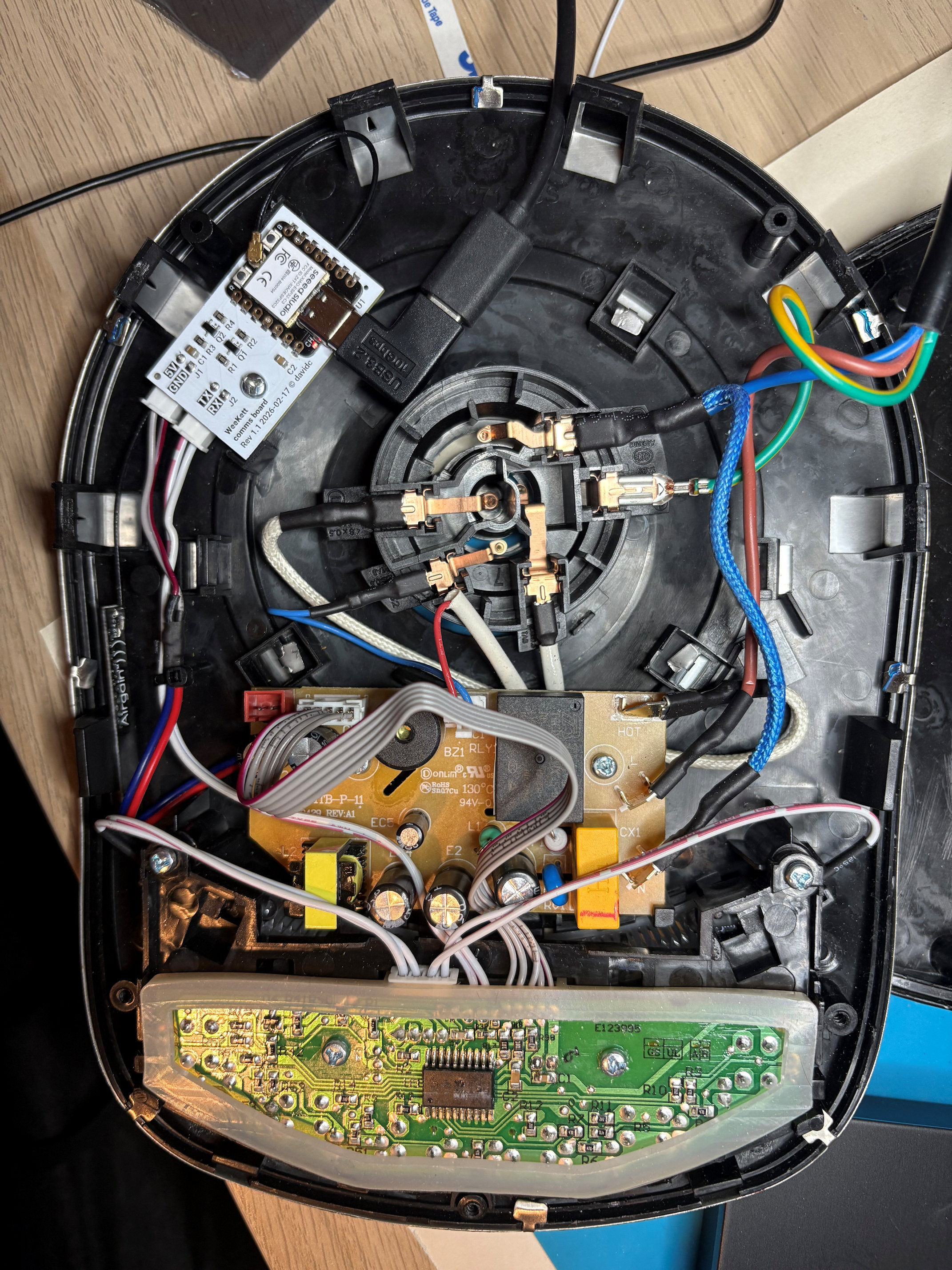
[C][tuya:087]: Product: '{"p":"01rtpfyd3amxdsps","v":"1.0.0","m":0}'Everything from a hardware perspective was now complete, and although I did not seal up the base until I was confident in OTA firmware updates, I screwed the board into the mounting position of the original Tuya carrier and stuck the antenna to the side of the case:
The PCB design can be found in my Github repository. Feel free to get it produced or even assembled yourself. I did receive 5, the minimum order, and I'll keep a couple of these as they'll be useful little ESP32 to 5V serial boards, but I have a couple spare and if anyone seriously wants to replace their WeeKett comms board, I'll ship them one in the UK for P&P (you'll need to provide a XIAO module).
Last steps
I needed to put some software on the device to expose the necessary controls to Home Assistant. In the final part of Kettle Quest, I'll go into my choices and present the final interface, and reflect on my accomplishments.