It's been pretty hot lately, and I decided I needed a fan in my study, and moreover I wanted a smart fan so I could control the use of the fan versus the air purifier automatically based on the temperature and whether the window is open. Initially I was open to a fan with a remote control, which I could control via an infrared blaster (albeit without feedback or live state), but what I really wanted was one with Zigbee or Wifi but not dependent on a cloud service.
I was eventually convinced to buy a Dreo tower fan because it has a manufacturer-supported Home Assistant integration that, at the time of writing, clearly states "direct control".
I should have given up and returned it when I realised the advertised "direct control" was a lie, and it is not at all direct - you have to create a Dreo account, install the app, connect it to a Wifi network that must have Internet access, and can only control it indirectly via "the cloud".
But there were some reports of people successfully flashing ESPhome on their Dreo fans, albeit with a strong warning not to try it on any other model. So I duly opened up the device and connected a couple of USB UARTs to sniff the traffic between Wifi module and MCU to see what I was dealing with.
I should have given up when I realised the protocol was nothing like documented by Pierre-David. But I saw something familiar, a 0x55AA at the start of every packet - a clear indicator of the Tuya communication protocol. And the checksum at the end of the packet matched Tuya's algorithm too (sum of all packet bytes including magic word, modulo 256).
I should have given up when I realised that it was a severely butchered version of the Tuya protocol, that no existing Tuya support on ESPhome or Tasmota would be able to cope with. But by this time I had thoroughly voided my warranty and right-of-return, and was fully down the rabbit hole of reverse-engineering the protocol.
Warning
As you'll read in this article, Dreo seem to use very different setups and protocols for different devices. My device is a DR-HTF018S revision 1.1, EU model, bought in June 2026. I actually ordered the DR-HTF001S so this may be an update of that. Don't follow anything in this article without verifying for yourself what protocol you're dealing with. One way to be sure is to attach USB UARTs as I describe below and run my protocol decoder to see if your packets are correctly decoded.
Internals
The fan consists of no fewer than three MCUs on three different PCBs.
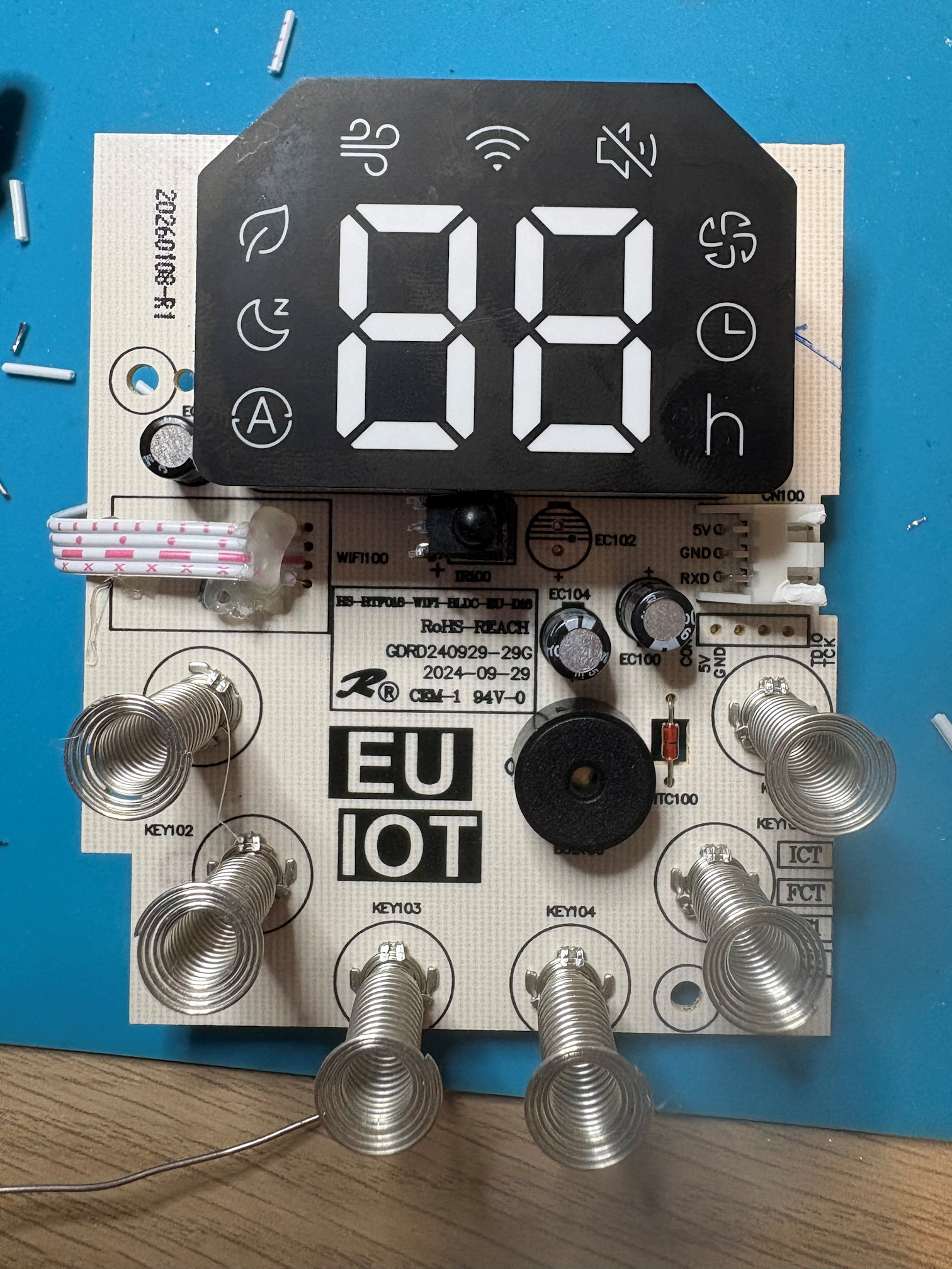
At the top of the fan is the main control board, which uses a SC95F8613B 8051-clone MCU, taking input from the capacitive touch buttons, driving the LCD, running the auto shutdown timer, etc.
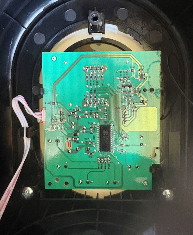
On the reverse side of this board are the capacitive buttons, display panel, and infrared receiver, as well as the wifi module on a daughterboard.
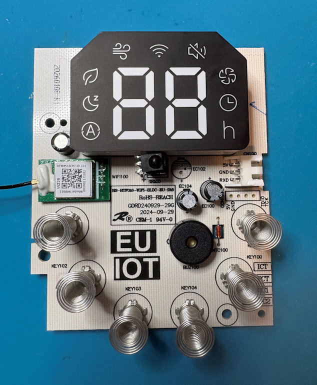
The module is an "MBL01". Searching for the FCC filing reveals the applicant was Hesung Innovation (Dreo) themselves, so it's not a standard module. Unfortunately the "user guide" doesn't have any detail, but the meagre specs listed are similar enough to the MBL02 found by Pierre-David that I assume it is just the same design with a different form factor.

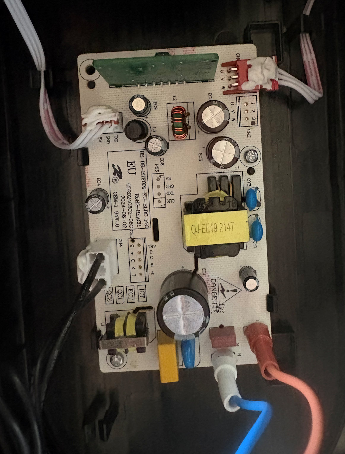
At the bottom of the fan is the power board with motor controllers. It is linked to the main control board via a 3-conductor cable (5v, GND and serial). Weirdly, it's labelled as TX on the power board and RX on the main control board, but given the main control board needs to be the one in charge, it can only be the other way around. I didn't bother to sniff this line because I want to keep the main control board (and buttons and display) intact.
Sniffing between main control and wifi daughterboard
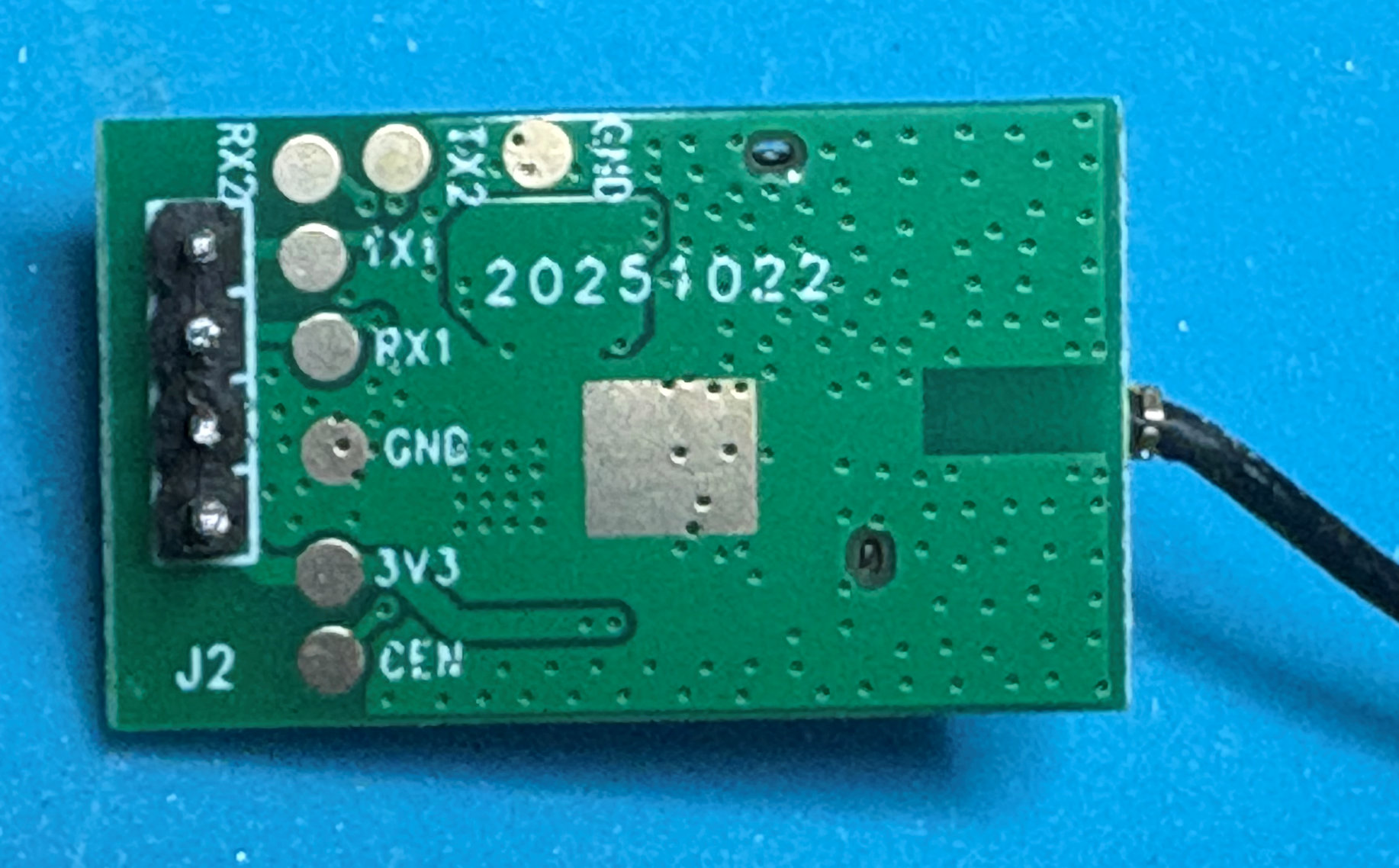
Bar some conformal coating, it was fairly easy to desolder the daughterboard and insert a four-conductor ribbon cable instead (I could have just soldered new wires in addition, but I had half a mind that eventually I'd replace this board with an ESP32).
After desoldering the module, the pins are helpfully labelled, and I even observed the same TX2/RX2 for debugging, although I didn't bother to connect to them.
I attached a USB UART to the RX and TX lines so I could snoop both directions and, after mucking around with the god-awful SerialTool, I eventually just dived into Python. You can find my Python code that decodes all messages I've witnessed, along with some sample captures, on my Github.
Protocol
There are a few similarities with the Tuya protocol, but quite a few differences too. As I don't believe this is a Tuya wifi module, someone seems to have just taken a protocol they are familiar with, and butchered it for their needs.
The serial format is 115200 8N1. All values are big-endian.
Header
The header starts with 55 AA like Tuya, even though doesn't really match any of the Tuya protocol versions.
The next byte is always 0; it could be a version number like in Tuya, but this still doesn't match Tuya protocol version 0.
The next byte seems to be a sequence number. It's always repeated by the other end in a response. It also increases by one for each packet when doing heartbeats, although there seems to be a different sequence number maintained for each different command.
The next byte is the command number, which in many cases mirrors the Tuya protocol's commands.
I have observed the next byte to always be 0.
The final two bytes of the header are the length of the payload (i.e. excluding the checksum).
For example in the packet "55aa0073000000010174" (Responding to your heartbeat, I am alive and haven't just rebooted):
| Bytes | Purpose | Example | Meaning |
|---|---|---|---|
| 0-1 | Magic number (always 55 AA) | 55 AA | |
| 2 | Unknown/Version? (always 00) | 00 | |
| 3 | Sequence number | 73 | In this case, since it's a response, the 73 was copied from the request |
| 4 | Command | 00 | Heartbeat |
| 5 | Unknown (always 00) | 00 | |
| 6-7 | Payload length | 00 01 | 1 byte payload |
Checksum
The final byte of the packet (which you find after the header's specified number of payload bytes) is the checksum. This is calculated as per the standard Tuya algorithm, i.e. sum up all the bytes up to this point (including all bytes of the header), modulo 256.
Again using the packet "55aa0073000000010174", the header+payload bytes are "55aa00730000000101", which if we sum up and take the last byte, we get 74. (Interesting aside, it is no coincidence that in these small heartbeat packets the checksum is nearly the same as the sequence number, because 55+AA=FF).
Payload
The payload contents depends on the type of command:
Command 0x00 (Heartbeat)
Request (Wifi-->MCU): no payload.
Response (Wifi<--MCU): a single byte that mirrors Tuya's usage - 00 if this is the first heartbeat since power-on, 01 otherwise.
Command 0x01 (Get MCU info)
Request (Wifi-->MCU): no payload.
Response (Wifi<--MCU): an ASCII string containing the MCU part number and the software version number that matches what's shown in the app (in my case, the full string is 001+SC95F8613B/EU+0.0.8).
Command 0x03 (Report wifi module status)
Request (Wifi-->MCU): Two bytes, the first seems to be the pairing status and the second is always 0.
Response (Wifi<--MCU): no payload.
I have observed the first status byte go 01->02->03->05 during boot-up. It seems to be used by the MCU to control the wifi status icon on the display: 03 triggers the icon to briefly flash, 05 triggers it to turn on permanently.
Command 0x04 (Reset wifi module)
Request (Wifi<--MCU): no payload.
Response (Wifi-->MCU): no payload.
This is triggered by holding the oscillation button on the panel for 5 seconds, sending a reset command to the wifi module (which seems to just reboot and go through the startup sequence and not actually reset anything).
Command 0x06 (Change DP)
Request (Wifi-->MCU): A full datapoint structure (format below) to change. Possibly if this really mirrors Tuya, you might be able to send multiple DPs to change at once, but I did not observe this.
Response (Wifi<--MCU): no payload.
Following the acknowledgement, the MCU sends a full report (command 0x07) which in turn is acknowledged.
Command 0x07 (Full DP status report)
Request (Wifi<--MCU): A list of full datapoint structures (format below) of all current datapoints and their values. In this case, all datapoint are sent.
Response (Wifi-->MCU): no payload.
The MCU will send these unsolicited every 60 seconds (as long as a timer has been running at any point since boot-up). It will also send them immediately after a value is changed either through the panel or by command. It will also send them in response to command 0x08 (but in that case won't get a further acknowledgement).
Command 0x08 (Request DP status report)
Request (Wifi<--MCU): no payload.
This is sent at start-up to get current values. The MCU then replies with command 0x07 using the same sequence number. That 0x07 is not acknowledged because it is itself a reply. This weird behaviour means the command changes but it's actually still a response.
Command 0x0E (DP changed)
Request (Wifi<--MCU): Three bytes that I haven't figured out.
Response (Wifi-->MCU): no payload.
This is sent by the MCU, after a status report, when a value has been changed by local panel control. I'm unable to figure out the format, since it doesn't contain the dpId, and is too short to contain the new value. I decided to ignore this command since we always receive a status report with command 0x07 in addition anyway.
Datapoint structure
When setting a DP, there is one of these structures; when reporting the current DP values, there are multiple sequential structures. The datapoint types I have observed mirror Tuya's, but there are some difference in the structure.
| Bytes | Purpose |
|---|---|
| 0 | Datapoint ID |
| 1 | Flags? This is set to 0 normally, but set to 1 by the Wifi module in a change command, and set to 1 for all DPs in the status report the MCU sends back immediately following a change. |
| 2 | Datapoint type (1=boolean, 2=integer, 4=enum) |
| 3-4 | Data length |
| 5- | Data |
Datapoint IDs
The following datapoints are returned in the full status report, of which I have identified most:
| dpId (dec) | Type | Meaning |
|---|---|---|
| 1 | boolean (1) | Fan power status (true=on, false=off) |
| 2 | boolean (1) | Display always on (true=always on, false=auto off) |
| 3 | enum (4) | Mode (1=normal, 2=natural, 3=sleep, 4=auto) |
| 4 | enum (4) | Fan speed (1-9) |
| 5 | boolean (1) | Beeper (true=on, false=silent). Beeper is always turned to silent when mode is changed to sleep. |
| 6 | int32 (2) | Auto-off timer (in minutes) |
| 7 | int32 (2) | Unknown (always 0) |
| 8 | boolean (1) | Oscillation (true=on) |
| 9 | enum (4) | Unknown (always 0) |
| 11 | int32 (2) | Temperature (in Fahrenheit) |
| 12 | boolean (1) | Unknown (always false) |
Standard sequence of operations
When power is first applied:
- the MCU sends an immediate unsolicited DP status report, although in my observation this isn't acknowledged because the Wifi module hasn't yet booted up
- an initial heartbeat exchange occurs, which has a status of 00 because it's the first the MCU has responded to since power-on
- the Wifi module sends a module status report of 0000 to the MCU, which is acknowledged
- the Wifi module sends a MCU info request, which is responded to, in my case with "001+SC95F8613B/EU+0.0.8"
- the Wifi module sends further module status reports of 0100, 0200 a few times, 0300 a few times, and eventually 0500, which are responded to, presumably as it connects to the cloud
- the Wifi module sends an immediate DP status request 08, which is responded to with the standard DP report 07 with the same sequence number (so it is not acknowledged)
- another MCU info request and immediate DP status request are sent around the time module status reaches 0500, probably triggered by the cloud.
When nothing changes:
- a heartbeat is sent by the Wifi module and responded to by the MCU every 10 seconds
- an unsolicited DP status report is sent by the MCU and acknowledged by the Wifi module every 60 seconds (this may only happen if you have run an auto-shutdown timer at any point since boot-up, implying that this actually runs on the countdown timer task, so you need to manually request reports if you want things like temperature to update regularly).
When a button is pressed on the display board, changing the status of the device:
- the MCU sends a DP changed message, which the Wifi module acknowledges. I haven't decoded this, at three bytes it is too short and doesn't contain the dpId that has changed, but that doesn't matter because:
- the MCU sends an unsolicited DP status report, which the Wifi module acknowledges
When a command is issued from the cloud:
- the Wifi module issues a DP change command, which is acknowledged
- the MCU sends an unsolicited DP status report, which is acknowledged
When wifi reset is requested from the control panel (holding the oscillation button for 5 seconds):
- the MCU sends a reset module request, which is acknowledged
- the power-on sequence of module status changes, MCU status reports etc is repeated
- this seems to only reboot the wifi module; it remains connected to the cloud
Local control
At this point, having figured out the protocol and the important datapoints, I had a choice: I could either try compiling ESPhome for the existing wifi module, or I could replace it entirely.
While Pierre-David's writeup has a lot of info on how he managed to flash his module, this fan has a slightly different model, and it uses a chip I'm not familiar with. And, although he's provided the encryption keys, I've never had any experience flashing it.
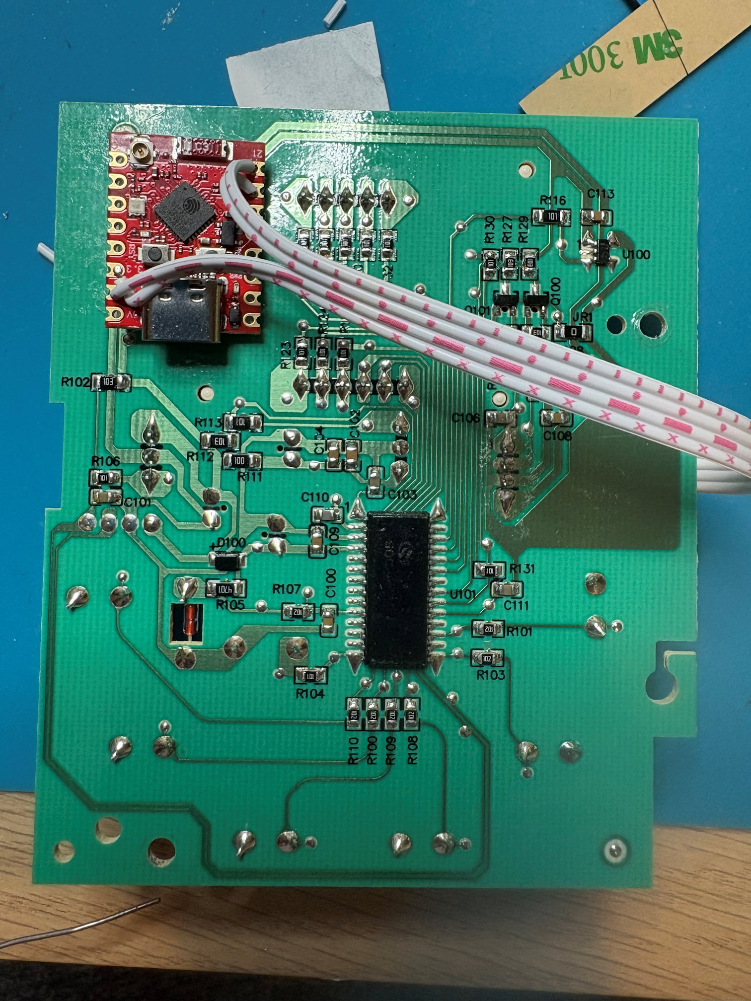
And especially for me, since I already had it open and the module desoldered, the simplest thing was to use an ESP32-C3 supermini module to replace the wifi module entirely (made especially convenient by the fact that the UART communication is 3.3V so no level shifters are required, and I'd already soldered in a ribbon cable I could connect directly to the supermini pins).
However, I suggest anyone following along with this fan tries to blend the best of both worlds - use the work I've done and code I've written for ESPhome to compile a binary for the existing wifi module, and use his method to flash it to the device. That way you may not even need to open it up. Let me know how you get on and I'll update here or link to your write-up.
ESPhome addon
Being a rather bespoke protocol, this was going to require either very complicated lambdas, or a custom ESPhome component. I opted for the latter as it would be much easier to read, especially for other users who would not need any code in their yaml file.
As it was conceptually similar to Tuya MCU, I took a copy of the Tuya component, stripped out all the commands that didn't exist, amended the ones that were different, removed the data point types that I'd not observed (since I couldn't be sure of their format), and changed the startup state machine. Then amended the wire protocol to match my reverse-engineering. I also copied the Tuya sub-components that were relevant to the datapoints I'd observed (number, switch, binary sensor, select, sensor, and, of course, fan).
This component lives at github.com/davidc/dreo-protocol and you can import it using simply:
external_components:
  - source: github://davidc/dreo-protocol
A full configuration for the HTF018S using an ESP32C3 supermini can also be found there, noting that you will need to insert your own wifi credentials and secrets.
And then you have the full functionality of the device exposed in Home Assistant:
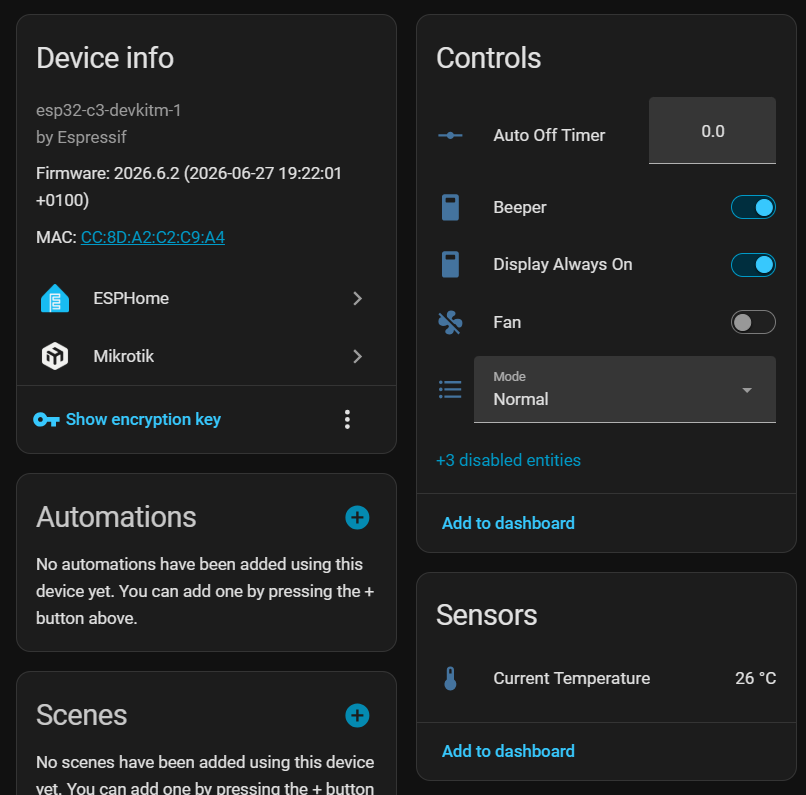
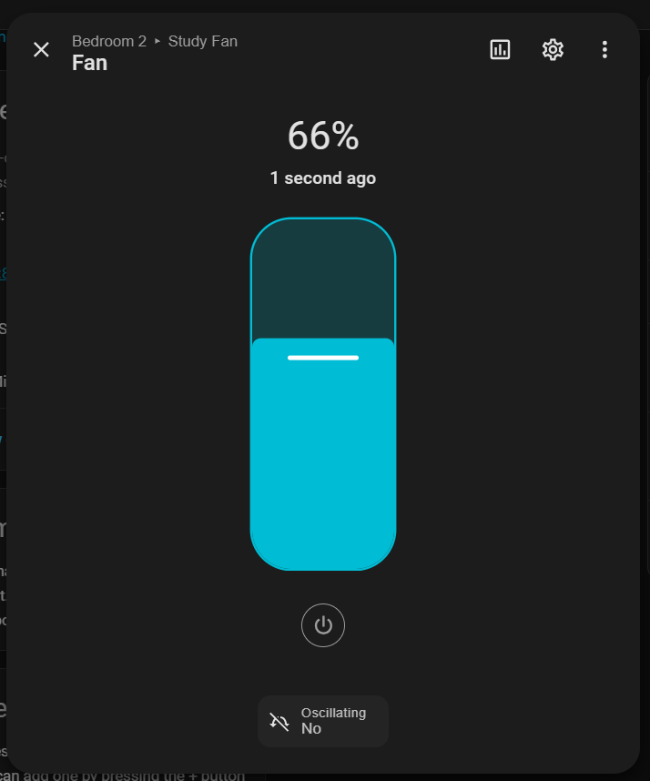
Complete with a native fan entity that includes oscillation control:
Reassembly
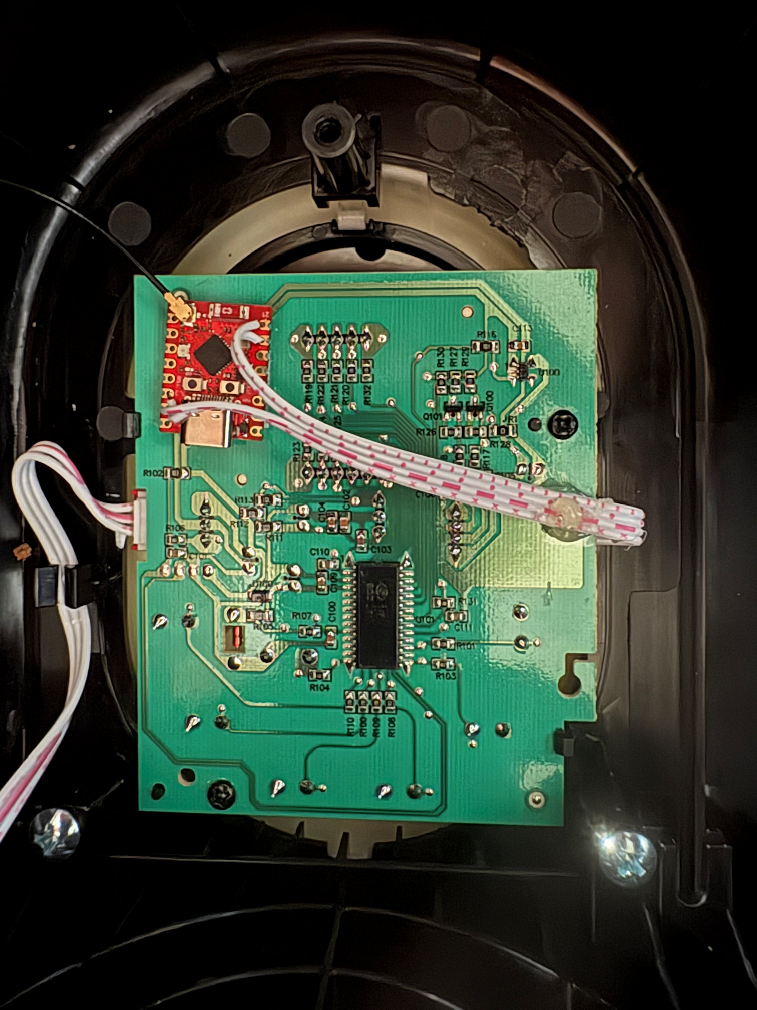
All of the above was done with the controller board removed from the fan - I knew the communication with the power board was unidirectional so the existence or non-existence of an actual attached fan was irrelevant to the functionality of either the controller board or the wifi module.
With ESPhome flashed and able to update OTA, it was time to seal things up and give it a try. As this board was going to feel a lot of vibration from the fan, I attached a liberal blob of hot glue to keep the 26AWG ribbon cable secure.
And attached the ESP32 with some velcro tape
Then reinserted the controller board into the case, sticking the antenna to the side.
And here is a short video of it in operation.
Final thoughts
I impressed myself getting this all done in well under a day since the fan arrived, but of course I've had plenty of recent experience doing a similar thing with the WeeKett and had all the components I needed to hand. Completed just in time for the end of the heatwave (at least this one).
Final final thought. In true EEVblog spirit ("don't turn it on, take it apart"), I tore the whole thing down and did all of the above work before even turning the fan on for the first time. It turns out that, despite its size and huge cost, it's actually a terrible fan: the air speed is very low for such a big fan, and the noise is incredible for one so weak (and the noise from the oscillation is even worse). I'm definitely not going to be able to sleep with it on. I would return it if I hadn't already thoroughly voided my right to do so. If you don't already have this fan, I'm sure there are better options.