I've started working on implementing a controller for Paxton readers. I have a KP50 (Net2 fob reader and PIN pad) and it comes with an RJ45 plug attached. There's no documentation I can find about the pinout, so here's what I've figured out.
The colours of the cable in the RJ45 plug are easy to see:
| Pin | Colour | |
|---|---|---|
| 1 | Yellow | |
| 2 | Blue | |
| 3 | Green | |
| 4 | Orange | |
| 5 | Brown | |
| 6 | Purple (or White) | |
| 7 | Black | |
| 8 | Red | |
Normally an installer will cut the plug off and wire it directly into the Paxton controller. These have a label identifying which colour goes where, and images are easily found on the Internet, such as on Paxton's own site.
Putting the two together, we get the full pinout of the Paxton RJ45 connector:
| Pin | Paxton Colour | T568B Colour | Purpose | ||
|---|---|---|---|---|---|
| 1 | Yellow | White/Orange | Data | ||
| 2 | Blue | Orange | Clock | ||
| 3 | Green | White/Green | Green LED | ||
| 4 | Orange | Blue | Amber LED | ||
| 5 | Brown | White/Blue | Red LED | ||
| 6 | Purple (or White) | Green | Media detect? | ||
| 7 | Black | White/Brown | 0V | ||
| 8 | Red | Brown | 12V | ||
I've put the T568B colours for reference as I used a short length for testing, but it's obviously not a good idea to have clock and data on the same twisted pair over any distance.
Things I've discovered so far
The LED pins should be pulled to 0V to light the LED.
The clock and data pins are actually 5V so can feed my logic analyser directly. They default to high (0). Data is available on clock falling edge, high is 0, low is 1.
"Media detect" appears to be unconnected on my reader. On some controllers, this pin is labelled as "Media detect", on others it is unlabelled.
The keypad beeps on its own when a fob is read or a button is pressed; I can't control this, but I can control the LEDs for feedback. The backlight on the keypad also appears to be fixed.
If you add a long-range reader to a reader, according to the documentation it reprograms the original reader to enable long range reading. The pinout gives no clue how this is achieved and I don't have a need for a long-range reader, but possibly the clock and data can be driven from the other end too.
Decoding
I'm using this this sigrok decoder plugin which decodes both fob reads and PIN keypad presses.
A Net2 fob read gives [lead in]-b-[card number]-f-[parity]-[lead out]. Apparently a Switch2 fob has extra data and looks like [lead in]-b-[something]-d-[something]-f-[parity]-[lead out].
A keypad press gives [lead in]-b-[keypress]-f-[parity]-[lead out], first with the keypress, then a moment later with keypress c99e (key released).
The keypresses decode as follows:
| 1 c00e |
2 c01e |
3 c02e |
| 4 c03e |
5 c04e |
6 c05e |
| 7 c06e |
8 c07e |
9 c08e |
| * c10e |
0 c09e |
# c11e |
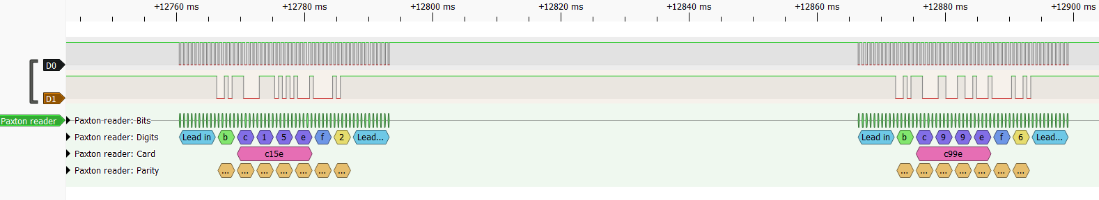
| Bell c15e |
No matter what key is pressed, it is followed by another message with c99e ~70ms later when the last key is released. If you press and hold a key, that key's message is generated; pressing additional keys while it's held does not generate additional messages. Holding the original key, then holding a different key and releasing the original key does not generate a release message; the c99e is generated only when the last key is released.
Here's me pressing the bell button:
The protocol is pretty self-explanatory from the decoder's source code and the accompanying references, so building a controller should be fairly easy once the parts arrive. Thanks to en4rab for his work on that.