It's been a long time since I've played with any microelectronics - the last time was about 15 years ago for my A/S level Electronics project with a venerable 1802 processor, already 20 years old at the time. I wired up a massive array of LED matrix displays and had it controlled by an 1802, one SRAM with program code, another with display data, and around 10 breadboards worth of demuxes, ripple counters and drivers. It was pretty dim, but it worked.
I've been meaning to experiment with more recent ones ever since, but since my electronics workshop was always located somewhere other than where I was living, I never got around to it. But finally, I've now managed to bring most of my components over to Berlin and have started playing around.
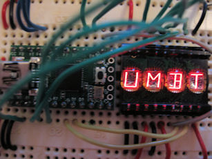 I'm currently trying out the amazing Teensy USB, an ATMega32U4 on a PCB about the size of the first joint of my thumb, which arrived today. Looking for a simple LED matrix to interface it with, I instead found a DL2416 I had swiped off something almost two decades ago. It's a beautiful retro-looking LED segmented alphanumeric display, but I could never find the data sheet for it at the time. Now, thanks to the magical Internet, I have it.
Not only is it a gorgeous piece of kit, it's actually very smart inside. It has a memory for each character, two address lines (for the four characters), and 7 data bus lines (although D6 and D5 are always inverse of each other, so I ran it through an inverter to save a data pin). Two chip enable pins make it easy to trigger - it only needs 70ns to complete a write. It also has a cursor and display blanking facility - the latter of which you can pulsate to alter the brightness - though I haven't used either. Its character set even almost-directly corresponds to ASCII 0x20-0x5f.
Connections
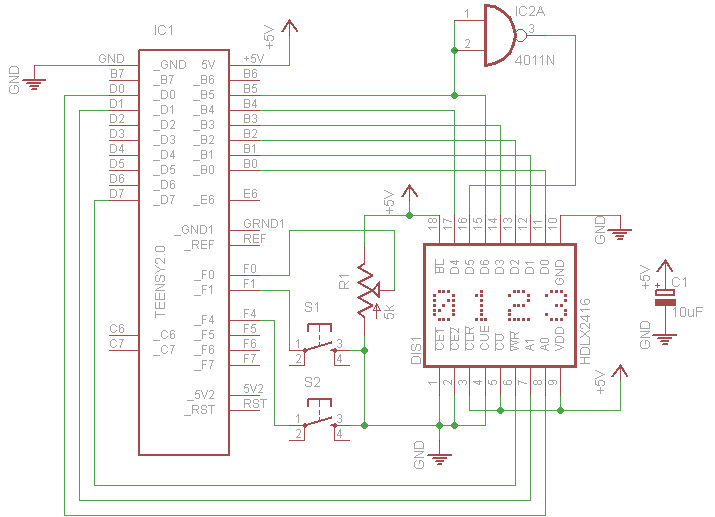
On the Teensy, I wired up PB0-5 to the display's D0-4,6 (and D5 via a spare NAND gate as an inverter) as the data bus. PD0-1 are wired to A0-1 as the address bus. PD7 I wired to ~WR. So to write a character, I just present the appropriate data and address values, and flash PD7 low for a microsecond.
DL2416 pinout:
~CE1, ~CE2 (chip enable) - hardwired low as I don't address anything else on this bus at present.
~CLR (display clear) - hardwired high.
CUE (cursor enable) - hardwired low.
~CU (cursor select) - hardwired high
~WR (write) - to PD7.
A1, A0 (digit select) - to PD1, PD0.
VCC - +5v from USB.
GND - 0v from USB.
D0-4,6 (data input) - to PB0-5.
D5 - is just D6 run through an inverter.
~BL (display blank) - hardwired high.
In addition, since I only just got the Teensy and wanted to play with inputs as well, I have a 5kohm trimmer between Vcc and Gnd connected to ADC0 (PF0), a switch connected to PF1, and a push button connected to PF4. The trimmer shows a voltmeter on the display, the switch toggles the on-board LED and changes the decimal point to an exclamation mark, and the push-button changes 'V' to 'U' as well as printing the voltage to the USB debug channel.
Circuit Diagram
Code
And here's the code. It scrolls a message once, and then switches to voltmeter mode. You can use the #defines if you want to scroll a message forever, or not at all.
usb_debug_only and analog are from the the Teensy USB Debug and ADC tutorials respectively.
#include <stdio.h>
#include <string.h>

#include <avr/io.h>
#include <avr/pgmspace.h>
#include <util/delay.h>

#include <usb_debug_only.h>
#include <print.h>

#include <../libraries/analog/analog.h>

#define CPU_PRESCALE(n) (CLKPR = 0x80, CLKPR = (n))
#define CPU_16MHz       0x00

#define SCROLLMESSAGE 1
#define SCROLLMESSAGE_ONCE 1
#define USBDEBUG 1

inline int is_button_pressed(void) { return (PINF & (1<<4)) == 0; }
inline int is_switch_on(void) { return (PINF & (1<<1)) == 0; }

static void write_char(uint8_t pos, char ch);
static void write_str(const char *str);

int main(void)
{
	CPU_PRESCALE(CPU_16MHz);

#ifdef USBDEBUG
	usb_init();

	// Wait for USB host to enumerate us
	while (!usb_configured()) {
	}

	// Wait 1 second more to allow drivers to load
	_delay_ms(1000);
#endif

	// PB0-5 = data bus
	DDRB = 0x3f;

	// PD0-1 = address bus
	// (PD6 = on-board LED)
	// PD7 = ~WR
	DDRD = 0xff;
	PORTD = 1<<7; // keep PD7 high when not in use

	// PF0 - pot (ADC)
	// PF1 - switch
	// PF4 - button
	DDRF = 0x00;
	PORTF = 0x12;

	analogReference(ADC_REF_POWER);

#ifdef SCROLLMESSAGE
	const char *message = PSTR("DAVIDC!");
	int16_t len = strlen(message);
	int16_t pos = -3;

	while (pos < len) {

		for (uint8_t i=0; i<4; ++i) {
			if (pos + i < 0 || pos + i >= len) {
				write_char(3 - i, ' ');
			}
			else {
				write_char(3 - i, pgm_read_byte(message + pos + i));
			}
		}

		++pos;
#ifndef SCROLLMESSAGE_ONCE
		if (pos >= len) pos = -3;
#endif
		_delay_ms(500);
	}
#endif

	char tmpbuf[128];

	while (1) {
		int16_t reading = analogRead(0);
		double voltage = (50.0 * reading) / 0x3ff;
		voltage = round(voltage) / 10.0;
		sprintf(tmpbuf, "%f", voltage);

#ifdef USBDEBUG
		if (is_button_pressed()) {
			print("adc voltage = ");
			char *ptr = tmpbuf;
			while (*ptr != 0) {
				usb_debug_putchar(*(ptr++));
			}
			print("\n");
		}
#endif

		if (is_switch_on()) {
			tmpbuf[1] = '!';
		}

		if (is_button_pressed()) {
			tmpbuf[3] = 'U';
		}
		else {
			tmpbuf[3] = 'V';
		}
		write_str(tmpbuf);

		// Light on-board LED if the switch is on
		if (is_switch_on()) {
			PORTD |= (1<<6);
		}
		else {
			PORTD &= ~(1<<6);
		}

		_delay_ms(100);
	}
}


/*
 * Character set
 *  !"#$%&'()*+,-./
 * 0123456789:;<=>?
 * @ABCDEFGHIJKLMNO
 * PQRSTUVWXYZ[\]^_
 */

inline static char ascii_to_display(char ch)
{
	if (ch > 0x60 && ch < 0x7b)
		ch -= 0x20; // lower to upper case

//  if (ch > 0x20 && ch < 0x60)
    return (ch & 0x3f);
//	else return 0;
}

static void write_char(uint8_t pos, char ch)
{
	// Write address bus
	PORTD = (PORTD & ~0x03) | (pos & 0x03);

	// Write data bus
	PORTB = (PORTB & ~0x3f) | ascii_to_display(ch);

	// Strobe ~WR low (requires 70ns)
	PORTD &= ~(1<<7);
	_delay_us(1);
	PORTD |= (1<<7);
}

static void write_str(const char *str)
{
	for (int i=0; i<4; ++i) {
		if (str[i] == 0) {
			for (; i<4; ++i) {
				write_char(3-i, ' ');
			}
			return;
		}
		write_char(3-i, str[i]);
	}
}
Update 14/7: Instead of the inefficient _delay_us(1), I changed to using an assembler NOP instruction. This takes one clock cycle, which means that with the fastest 16Mhz clock speed, it takes 62.5 nanoseconds, so two are required to meet the 70ns requirement of the chip (although one seems to work fine for this unit). So:
	// Pause for at least 70ns
	asm volatile ("nop");
#if F_CPU > 14285714
	asm volatile ("nop");
#endif
Video
And here it is in action!
| Attachment | Size |
|---|---|
| Teensy and DL2416.jpg | 30.96 KB |
| Teensy Display circuit diagram.png | 10.93 KB |
DL2416
Hi,
I like your Teensy drive to revive the DL2416. I happen to have a couple of those displays, but do not have a Teensy module. I do have an Arduino 2009 board, though, and I wondered whether you could give me a hint on how to connect the DL2416 to this board, and how to change the program to drive it!
Maybe it's too much asking, I know...
Happy New year
Giampaolo